
User's Manual Part 2
30
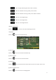
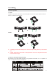
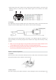
Letters A and B are marked respectively on the hub of the propeller, in the internal surface of the
propeller cap, and the motor rotor. Make sure signs of the three are the same in the installation and
dismounting.
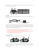
In installation, choose the same type of propeller with that on the motor rotor. Put the side with the
letter up and insert it to the spacer pin of the propeller in the electric motor. Press the performing
of the propeller to the card slot of the motor spindle in the direction vertical to the spacer pin.
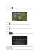
Rotate the performing for 90° to align the hole sides at two ends with the spacer pin and press it in.
In the end, rotate the propeller cap according to the direction shown in the cap.
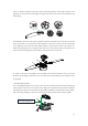
To remove, take down the propeller cap according to the direction shown in the cap. Lift the
propeller cap up slightly and rotate it for 90° to take down the performing. In the end, take down
the propeller.
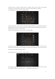
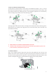
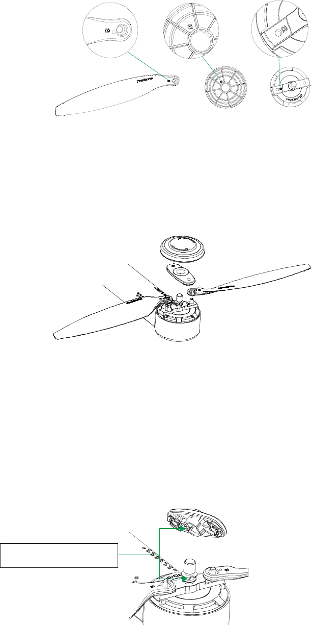
y Anti-Shooting Propellers
The anti-shooting propeller serves as the second security assurance besides the self-locking design
of the propeller cap. Even if the cap falls off in flight, this mechanism will prevent the propeller
from being ejected out. The card slot in the performing coordinates with that in the motor spindle.
Only when the performing is rotated to certain angel, it could be taken down from the spindle.
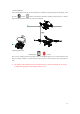
Anti-Shooting Device