
User guide

15
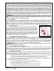
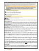
f) Suspension fork adjustment
The Stride R uses a dual pre-load adjustable suspension fork. The fork‘s dual adjustment
offers either a softer of firmer ride for smoothing out the bumps in your path. The pre-load
can be adjusted according to your weight and liking. You can easily adjust the
suspension performance by rotating the knobs at the top of each leg at the crown.
Chapter 6: Tire, Tube, Wheel and Axle Repair
The Stride R was designed for ease of servicing. Repairs are no more difficult than on
a traditional bicycle. Any neighborhood bicycle shop should be able to repair a flat,
change a tire or replace a wheel. Please review the following chapter on how to
remove and replace the front and rear wheel of your Stride R.
a) Removing the rear motor wheel
The wheel incorporates a motor wire quick disconnect for removing the wheel. To remove the wheel, follow these
instructions, it will only take a few minutes. Read the instructions fully before first attempting to remove the wheel.
Prior to removing the wheel, shift the bicycle into gear 7 or 8 (the small COG/sprocket on the rear cassette. It will be
easy to remove the wheel if the chain is at the end of the cassette. Make sure to spin the crank while shifting gears.
Next, turn the battery ignition key to the ―UNLOCK‖ position and remove the battery.
To work on your bicycle, it may be easier to turn the bicycle upside down by placing blankets on the ground and
resting the bicycle on the saddle and handlebar.
Locate the motor disconnect weather proof plug on the left side of the bike frame 6 inches from the motor axle and
separate the connector.
Locate the cable tie which ties the motor wire to the frame. Cut the cable tie with snips.
On each axle nut there is a rubber nut protector, remove these protectors simply by pulling on them. On the wired
side of the axle, slide the rubber protector up the wire only a few inches.
Using a wrench, turn counter clockwise each axle nut until the axle washers are loose.
Remove the wheel from the frame by pulling on the wheel.
The 8 speed freewheel mounted to the motor can be slid out away from the chain with no issue. The spring of derailleur may
cause the lower pulley to get in the way of removing the wheel. Simply pull the pulley out of the way.
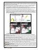
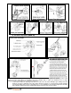
b) Installing the rear motor wheel
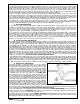
The rear motorized wheel easily installs onto the rear frame dropouts within a few minutes. Follow the instructions below on
installing the rear motor wheel. Your Stride R included additional cable ties with the User Guide. 1 cable tie will be needed to
install the motor. Read the instructions fully before attempting to install the wheel. (SEE PHOTOS NEXT PAGE)
Pull or push the rear derailleur lower pulley with chain out of the way of the dropouts.
Now check to make sure the chain is not in the way and align the wheel above (below if bike is on kick stand and not upside
down) the dropouts and pay attention to the lining up of the disk brake rotor into the brake caliper (between the pads).
Prior to inserting the wheel into the dropouts, pull the chain onto the cassette.
Slide the motor into the frame dropouts by aligning the axle into the dropouts. The axle has flat edges which require
the axle to enter the dropouts with the flat edges facing front and back. The axle with the motor wire protruding is to
enter the left side dropout (the left side is when standing behind the handlebar).
Each axle side has washers and a nut. Slide the washers over the axles and tighten nuts by hand.
Using a wrench, fully tighten axle nuts. Axle nuts should be tightened to 250 lb*in.
Plug motor connection by aligning arrows on each end of the connector and slide together.
Once connectors are plugged, you must test the connection. Install the battery as described in Chapter 8 ―Battery
Management‖ section c ―Installing and locking the battery‖. Turn the ignition key to ―ON‖ at the battery mount. LED
lights on throttle will light up displaying power to the motor. Pull the rear motor wheel off the ground (if the bicycle is
not turned upside down) and turn the throttle to test the motor. If the motor turns, the connection is solid. If motor
does not turn, turn key to ―OFF‖ position at battery mount and then check the motor connector to ensure a solid
connection has be made. Test again after checking.
After confirming a solid connection, use the cable tie to connect the motor cable to the side of the frame and once
tightened, cut off the extended amount.