
Instructions / Assembly


15
CAUTION: Two gas line installations at the same time are prohibited. The access plate to the simple switching means
shall not be opened while the heater is in operation.
This appliance can be used with propane or natural gas. It is shipped from the factory adjusted for use with propane. Only
a qualified installer or service technician can perform gas selection and connecting to gas supply.
CAUTION: To avoid gas leakage at the inlet of regulator, a qualified installer or service technician must use steel
or metal hex plug with sealant.
WARNING: Do not attempt to access or change the setting of the fuel selection means
Access to and adjustment of the fuel selection means must only be performed by a qualified service person when
connecting this appliance to a specified fuel supply at the time of installation.
Change of the selector setting to other than the fuel type specified at the time of installation could damage this ap-
pliance and render it inoperable.
The installer shall replace the access cover before completing the installation and operating this appliance.
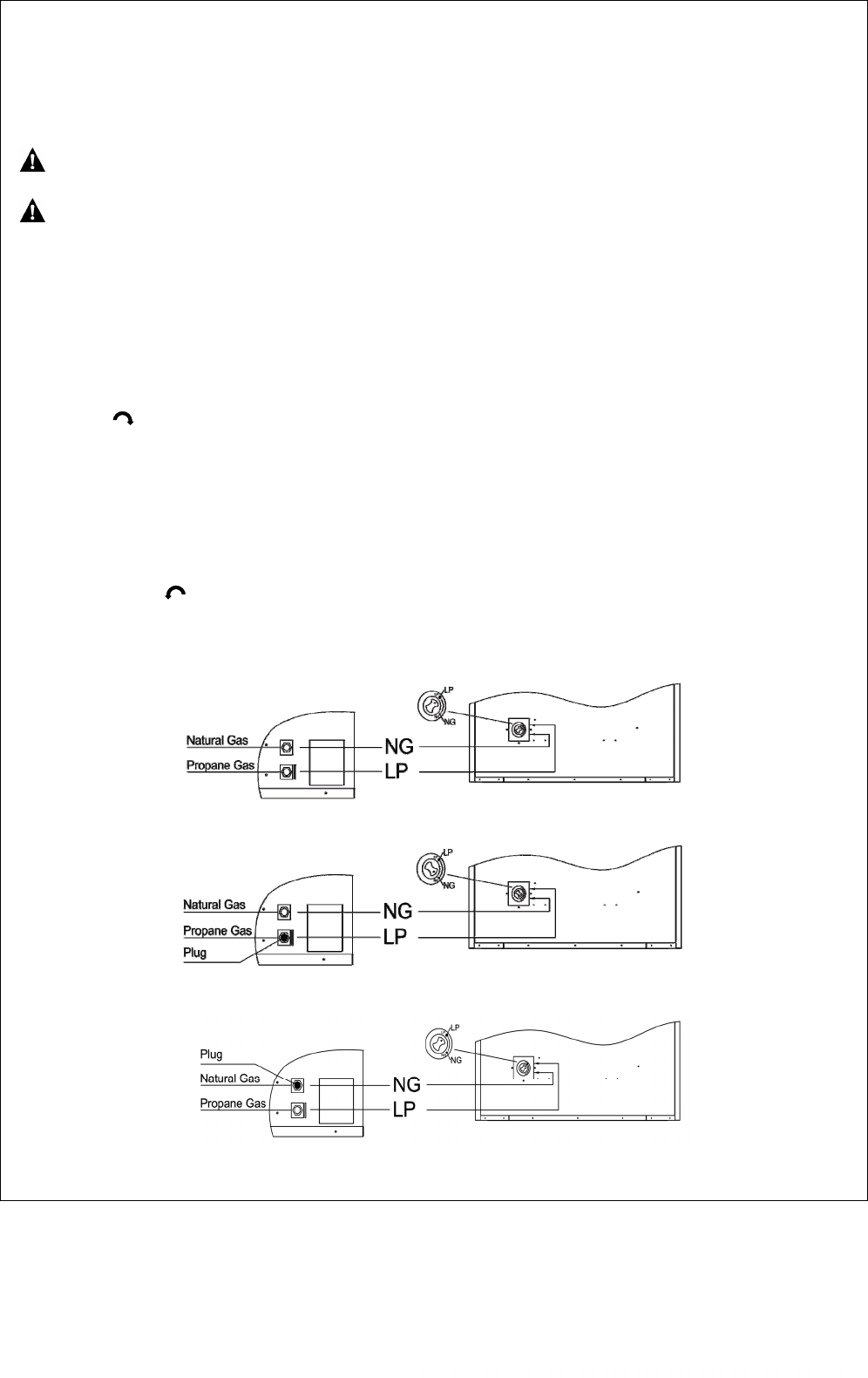
For changing from propane to natural gas supply
1. Remove bottom screw from cover plate, see Figure 13, and rotate to expose fuel selection device.
2. For NATURAL GAS, press in knob using a flat screwdriver with a blade the width of a quarter and turn knob
clockwise until the knob locks into the NG position (see Figure 14). Fuel selection device must be locked into the
NG position. Do not operate heater between locked positions!
3. Rotate and close cover over fuel selection device and reinstall screw.
4. Remove steel or metal hex plug (with wrench provided) from natural gas inlet of regulator and install into LP inlet of
regulator, use thread sealant to assure there are no leaks.
For changing from natural gas supply to propane supply
1. Remove bottom screw from cover plate, see Figure 13, and rotate to expose fuel selection device.
2. For PROPANE GAS, press in knob using a flat screw driver with a blade the width of a quarter and turn knob
counterclockwise until the knob locks into the LP position (see Figure 15). Fuel selection device must be
locked into either the LP position or the NG position.
3. Rotate and close cover over fuel selection device and reinstall screw.
4. Remove steel or metal hex plug from LP gas inlet of regulator and install into NG inlet of regulator, use thread
sealant to assure there are no leaks.
Figure 14
Figure 15
Figure 13