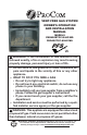
VENT-FREE GAS SYSTEM OWNER'S OPERATION AND INSTALLATION MANUAL MODELS FBD400RTCC-M-HC/MO FBD400TCC-M-HC/MO PFS ® US WARNING: If the information in this manual is not followed exactly, a fire or explosion may result causing property damage, personal injury or loss of life. — Do not store or use gasoline or other flammable vapors and liquids in the vicinity of this or any other appliance. — WHAT TO DO IF YOU SMELL GAS • Do not try to light any appliance.
TABLE OF CONTENTS Safety......................................................... 3 Specifications............................................. 5 Qualified Installing Agency......................... 5 Product Features........................................ 5 Product Identification.................................. 6 Unpacking.................................................. 6 Local Codes............................................... 6 Water Vapor: A By-Product Of Unvented Room Heaters....................
SAFETY IMPORTANT: Read this owner’s manual carefully and completely before trying to assemble, operate, or service this heater. Improper use of this heater can cause serious injury or death from burns, fire, explosion, electrical shock and carbon monoxide poisoning. Failure to follow these instructions will void the warranty. Only a qualified installer, service agent, or local gas supplier may install and service this product.
SAFETY 1. Do not place Propane/LP supply tank(s) inside any structure. Propane/LP supply tank(s) must be placed outdoors. 2. This heater should not be installed in a bedroom or bathroom. 3. This heater needs fresh air ventilation to run properly. This heater has an Oxygen Depletion Sensing (ODS) safety shutoff system. The ODS shuts down the heater if not enough fresh air is available. See Air for Combustion and Ventilation, pages 7 through 9. If heater keeps shutting off, see Troubleshooting, page 27. 4.
SPECIFICATIONS MODELS FBD400TCC-M-HC/MO Gas Type Natural Propane/LP Maximum Input Rating 32,000 BTU/Hr 32,000 BTU/Hr Minimum Input Rating 14,500 BTU/Hr 24,500 BTU/Hr Regulator Pressure Setting 4" W.C. 9" W.C. Inlet Gas Pressure* Max. 10.5" W.C. (inches of water) Min. 5" W.C. MODELS Max. 14" W.C. Min. 11" W.C. FBD400RTCC-M-HC/MO Gas Type Natural Propane/LP Maximum Input Rating 32,000 BTU/Hr Minimum Input Rating Regulator Pressure Setting 32,000 BTU/Hr N/A N/A 4" W.C. 9" W.C.
PRODUCT IDENTIFICATION Hood Screen Logs Heater Controls (Inside Panel) Figure 1 - Vent-Free Fireplace Insert UNPACKING 1. 2. 3. 4. 5 Remove top inner pack. Tilt carton so that heater is upright. Remove protective side packaging. Slide heater out of carton. Remove protective plastic wrap. 6. 7. 8. 9. Hold the screen, lift, and pull forward. Remove log set by cutting plastic ties. Carefully unwrap log. Check for any shipping damage.
WATER VAPOR: A BY-PRODUCT OF UNVENTED ROOM HEATERS Water vapor is a by-product of gas combustion. An unvented room heater produces approximately one (1) ounce (30 mL) of water for every 1,000 BTUs (0.3 KWs) of gas input per hour. Unvented room heaters are recommended as supplemental heat (a room) rather than a primary heat source (an entire house). In most supplemental heat applications, the water vapor does not create a problem.
AIR FOR COMBUSTION AND VENTILATION Unusually Tight Construction The air that leaks around doors and windows c. caulking or sealants are applied to areas may provide enough fresh air for combustion such as joints around window and door and ventilation. However, in buildings of unframes, between sole plates and floors, usually tight construction, you must provide between wall-ceiling joints, between wall additional fresh air.
AIR FOR COMBUSTION AND VENTILATION The space in the above example is a confined space because the actual Btu/Hr used is more than the maximum Btu/Hr the space can support. You must provide additional fresh air. Your options are as follows: A. Rework worksheet, adding the space of an adjoining room. If the extra space provides an unconfined space, remove door to adjoining room or add ventilation grills between rooms. See Ventilation Air From Inside Building. B. Vent room directly to the outdoors.
INSTALLATION NOTICE: This heater is intended for use as supplemental heat. Use this heater along with your primary heating system. Do not install this heater as your primary heat source. If you have a central heating system, you may run system’s circulating blower while using heater. This will help circulate the heat throughout the house. In the event of a power outage, you can use this heater as your primary heat source. WARNING: A qualified service person must install heater. Follow all local codes.
INSTALLATION GAS SELECTION This appliance is factory preset for propane/LP gas. No changes are required for connecting to propane/LP. Only a qualified installer or service technician can perform gas selection and connecting to gas supply. CAUTION: Two gas line installations at the same time are prohibited. The access plate to the simple switching means shall not be opened while the heater is in operation.
INSTALLATION 1. 2. 3. 4. For changing from natural gas supply to propane supply: Remove bottom screw from cover plate located on left side of heater (see Figure 4, page 11). Rotate to expose fuel selection device. For propane gas, press in knob using a flat screwdriver with a blade the thickness of a quarter and turn knob counterclockwise until the knob locks into the LP position (see Figure 6). Fuel selection device must be locked in the LP position. Do not operate heater between locked positions.
INSTALLATION CONNECTING TO GAS SUPPLY WARNING: A qualified service technician must connect heater to gas supply. Follow all local codes. WARNING: This appliance requires a 3/8" NPT (National Pipe Thread) inlet connection to the pressure regulator. WARNING: Do not overtighten gas connections. WARNING: For natural gas, Never connect heater to private (non-utility) gas wells. This gas is commonly known as wellhead gas. CAUTION: For propane/ LP gas, never connect heater directly to the gas supply.
INSTALLATION Typical Inlet Pipe Diameters Use 3/8" black iron pipe or greater. Installation must include an equipment shutoff valve, union, and plugged 1/8" NPT tap. Locate NPT tap within reach for test gauge hook up. NPT tap must be upstream from heater (see Figure 8). IMPORTANT: Install an equipment shutoff valve in an accessible location. The equipment shutoff valve is for turning on or shutting off the gas to the appliance. For propane/LP installations, apply pipe joint sealant lightly to male threads.
INSTALLATION CHECKING GAS CONNECTIONS WARNING: Test all gas piping and connections, internal and external to unit, for leaks after installing or servicing. Correct all leaks at once. WARNING: Never use an open flame to check for a leak. Apply a noncorrosive leak detection fluid to all joints. If bubbles form, there is a leak. Correct all leaks at once. PRESSURE TESTING GAS SUPPLY PIPING SYSTEM Test Pressures In Excess Of 1/2 PSIG (3.5 kPa) 1.
INSTALLATION INSTALLING LOGS WARNING: Failure to position the parts in accordance with these diagrams or failure to use only parts specifically approved with this heater may result in property damage or personal injury. 6. Insert the pin on log #6 into the hole on log #3 (see Figures 15 and 16, page 17). IMPORTANT: Make sure logs do not cover any burner ports. It is very important to install the logs exactly as instructed. Do not modify logs. Use only logs supplied with heater.
INSTALLATION Pin for Log #5 Hole for Log #6 Log #5 Log #4 Figure 15 - Installing Log #4 Log #6 Figure 16 - Installing Log #5 and #6 INSTALLING BATTERIES Type of Battery Qty. Ignitor Remote Control Remote Receiver AAA AAA AA 1 2 or 3* 4 Figure 17 - Installing Battery in Ignitor Receiver and Remote Control Batteries are required in both the Remote Control (Transmitter) (2 AAA size) and Receiver (4 AA size) (see Figure 18). Note: Be sure batteries are placed correctly.
OPERATION FOR YOUR SAFETY READ BEFORE LIGHTING WARNING: If you do not follow these instructions exactly, a fire or explosion may result causing property damage, personal injury or loss of life. A. This appliance has a pilot which must be lighted by hand. When lighting the pilot, follow these instructions exactly. B. BEFORE LIGHTING smell all around the appliance area for gas. Be sure to smell next to the floor because some gas is heavier than air and will settle on the floor.
OPERATION 7. With control knob pressed in, push down and release ignitor button. This will light pilot. The pilot is attached to the rear of the burner. If needed, keep pressing ignitor button until pilot lights. Note: If pilot does not stay lit, refer to Troubleshooting, pages 27 though 29. Also contact a qualified service technician or gas supplier for repairs. Until repairs are made, light pilot with match. To light pilot with match, see Manual Lighting Procedure. 8.
OPERATION MODELS FBD400RTCC-M-HC/MO LIGHTING INSTRUCTIONS WARNING: You must operate this heater with the screen in place. Make sure screen is installed before running heater. NOTICE: During initial operation of new heater, burning logs will give off a paper-burning smell. Orange flame will also be present. Open damper or window to vent smell. This will only last a few hours. 1. STOP! Read the safety information, page 18. 2. Open screen. 3. Make sure equipment shutoff valve is fully open. 4.
OPERATION CAUTION: Do not try to adjust heating levels by using the equipment shutoff valve. WARNING: If input gas type is NG, make sure NG pilot burner ignites. If input gas type is LP, make sure LP pilot burner ignites. TO TURN OFF GAS TO APPLIANCE Shutting Off Heater Turn control knob clockwise OFF position. to the Shutting Off Burner Only (pilot stays lit) Turn control knob clockwise to the PILOT position. MANUAL LIGHTING PROCEDURE 1. Open screen. 2.
OPERATION Key Settings ON - Operates unit to on position, manually operated solenoid ON. OFF - Operates unit to off position, manually operated solenoid OFF. MODE - Changes unit from manual mode to thermo mode. SET - Sets temperature in thermo mode. TEMP Setting°F/°C Scale The factory setting for temperature is °F. To change this setting to °C, press the ON key and the OFF key on the remote control at the same time (see Figure 22). This will change from °F to °C.
OPERATION 1. Press the MODE key until the LCD screen shows the word ROOM. The remote is now in the thermostatic mode. 2. Press and hold the SET key until the desired set temperature is reached. The LCD screen set numbers will increase from 45° to 99° and then restart over at 45°. 3. Release the SET key. The LCD screen will display the set temperature for 3 seconds, then flash the set temperature for 3 seconds, then LCD screen will default to display the room temperature. To Change The Set Temperature 1.
INSPECTING BURNERS IMPORTANT: Owner’s should check pilot flame pattern and burner flame pattern often. Incorrect flame patterns indicate the need for cleaning (see Care and Maintenance, page 25) or service. WARNING: Only a qualified service person should service and repair heater. This includes maintenance requiring replacement or alteration of components. PILOT FLAME PATTERN Figure 26 shows a correct pilot flame pattern. Figure 27 shows an incorrect pilot flame pattern.
CARE AND MAINTENANCE WARNING: Turn off heater and let cool before servicing. CAUTION: You must keep control areas, burner, and circulating air passageways of heater clean. Inspect these areas of heater before each use. Have heater inspected yearly by a qualified service technician. Heater may need more frequent cleaning due to excessive lint from carpeting, bedding material, pet hair, etc. WARNING: Failure to keep the primary air opening(s) of the burner(s) clean may result in sooting and property damage.
CARE AND MAINTENANCE ODS/PILOT Use a vacuum cleaner, pressurized air, or a small, soft bristled brush to clean. A yellow tip on the pilot flame indicates dust and dirt in the pilot assembly. There is a small pilot air inlet hole about 2" from where the pilot flame comes out of the pilot assembly (see Figure 31). With the unit off, lightly blow air through the air inlet hole. You may blow through a drinking straw if compressed air is not available.
TROUBLESHOOTING WARNING: If you smell gas: • Shut off gas supply. • Do not try to light any appliance. • Do not touch any electrical switch; do not use any phone in your building. • Immediately call your gas supplier from a neighbor’s phone. Follow the gas supplier’s instructions. • If you cannot reach your gas supplier, call the fire department. WARNING: Only a qualified service technician should service and repair heater. Make sure that power is turned off before proceeding.
TROUBLESHOOTING Problem Possible Cause Corrective Action ODS/pilot lights but flame 1. Control knob is not fully 1. Press in control knob fully. goes out when control pressed in. knob is released. 2. Control knob is not pressed 2. After ODS/pilot lights, keep in long enough. control knob pressed in 30 seconds. 3. Equipment shutoff valve is 3. Fully open equipment shutoff not fully open. valve. 4. Thermocouple connection is 4. Hand tighten until snug, and loose at control valve.
TROUBLESHOOTING Problem Possible Cause Corrective Action Slight smoke or odor 1. Residues from manufactur- 1. Problem will stop after a few during initial operation. ing process. hours of operation. Heater produces a whis- 1. Turning control knob to high 1. Turn control knob to low tling noise when burner position when burner is cold. position and let warm up for is lit. a minute. 2. Air in gas line. 2. Operate burner until air is removed from line. Have gas line checked by local gas supplier. 3.
PARTS MODELS FBD400RTCC-M-HC/MO FBD400TCC-M-HC/MO 22 1 5 20 3 15 14 4 7 OFF PILOT ON 18 2 6 LEA RN 21 ON RE MO TE OF F 8 9 19 10 TEMP 16 17 12 11 30 13 www.usaprocom.
PARTS MODELS FBD400RTCC-M-HC/MO FBD400TCC-M-HC/MO This list contains replaceable parts used in your heater. When ordering parts, follow the instructions listed under Replacement Parts on page 32 of this manual.
REPLACEMENT PARTS Note: Use only original replacement parts. This will protect your warranty coverage for parts replaced under warranty. PARTS UNDER WARRANTY Contact authorized dealers of this product. If they can’t supply original replacement parts, call Customer Service toll free at 1-866-573-0674 for referral information.
SERVICE HINTS When Gas Pressure Is Too Low • pilot will not stay lit • burners will have delayed ignition • fireplace will not produce specified heat • propane/LP gas supply might be low (propane/LP units only) You may feel your gas pressure is too low. If so, contact your local gas supplier. TECHNICAL SERVICE You may have further questions about installation, operation, or troubleshooting. If so, contact ProCom Heating, Inc. at 1-866-573-0674.
NOTES ________________________________________________________________________ ________________________________________________________________________ ________________________________________________________________________ ________________________________________________________________________ ________________________________________________________________________ ________________________________________________________________________ ____________________________________________________________________
NOTES ________________________________________________________________________ ________________________________________________________________________ ________________________________________________________________________ ________________________________________________________________________ ________________________________________________________________________ ________________________________________________________________________ ____________________________________________________________________
WARRANTY KEEP THIS WARRANTY Model ________________________________ Serial No. _____________________________ Date Purchased ________________________ Keep receipt for warranty verification. REGISTER YOUR PRODUCT AT WWW.USAPROCOM.COM IMPORTANT: We urge you to register your product within 10 days of date of installation, complete with entire serial number which can be found on the rating plate. Please fill out the warranty information above for your personal records. Retain this manual for future reference.