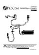
ITEM #0293810 BLOWER ACCESSORY MODEL #FIB100 Español p. 17 Questions, problems, missing parts? Before returning to your retailer, call our customer service department at 1-877-886-5989, 8:00 a.m - 4:30 p.m., EST, Monday - Friday or e-mail customerservice@usaprocom.com.
PACKAGE CONTENTS A B C E D PART A B C D E DESCRIPTION Power Cord Blower Temperature Sensor Connect Wire Rocker Switch 2 Quantity 1 1 1 1 1
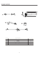
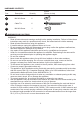
HARDWARE CONTENTS Part Description Picture (Shown to size) Quantity AA M4.2X8 Screw 6 BB Cable Tie 6 CC M4.0X8 Screw 1 Not shown to size WARNINGS AND CAUTIONS WARNING • Read all instructions and warnings carefully before starting installation. Failure to follow these instructions may result in a possible electric shock, fire hazard and will void the warranty. • Read all instructions before using this appliance. • If possible always unplug this appliance when not in use.
PREPARATION Before beginning assembly of product, make sure all parts are present. Compare parts with package contents list. If any part is missing or damaged, do not attempt to assemble the product. Contact customer service for replacement parts. Estimated Assembly Time: 30 minutes Tools Required for Assembly: Philips Screwdriver and Wire Cutter ASSEMBLY INSTRUCTIONS This blower contains assembly instructions for the following models and item numbers.
Fig. 2 2. Unscrew two screws on heat insulation board cover and draw it out. See Fig. 2. Fig. 3 3. Affix temperature sensor to heat insulation board cover with M4.2X8 screws (AA). See Fig. 3. c AA Hardware Used AA M4.2X8 screw x2 Fig. 4 4. Insert wires into the space between wire protecting board and shell; Fix the wires to the top cover with wire fixture. See Fig. 4.
Fig. 5 5. Connect temperature sensor (C) with connect wire (D. Install the cover according to Figure 2, then fix the upper fire box according to Fig. 1. See Fig. 5. D C Fig. 6 6. Unscrew and remove panel on the left side. See Fig. 6. (For Model # CRHFD32RT-MMO (Item # 0293807), FBD32 series only) Fig. 7 7. Remove blower access panel. See Fig. 7.
Fig. 8 8. Insert blower (B) into the bottom space of burner pan. Pay attention not to touch wires inside. See Fig.8. B Fig. 9 9. Set blower (B) plane and fix it onto two brackets of shell board. Make sure blower (B) is installed into the slots.See Fig. 9. Install Install Blower Blower Into slots Into slots B Fig. 10 10. Affix blower (B) with M4.0X8 screws (CC), after, manually install it into slots. See Fig. 10. cc Hardware Used CC 7 M4.
Fig. 11 11. Mount blower onto blower access panel. See Fig. 11. (For PC32VFC and PC36VFC series only). Fig. 12 12. Attach the power cord (A) to the fireplace with M4.2X8 screws (AA) on the top cover. See Fig. 12. AA A Hardware Used AA M4.2X8 screws x3 Fig. 13 13. Affix the grounding terminal with M4.2X8 screw (AA). See Fig. 13. AA Hardware Used AA 8 M4.
Fig. 14 14. Insert the male port of blower (B) and in to the corresponding female port. See Fig. 14. B Female Port Port Male MalePort Port Fig. 15 15. Connect the port and shell board with linker (male port) into the three wires with protecting jacket (please refer to linker (female port) (red, yellow and black) with grounding label); Put protecting jacket into rocker switch (E) corresponding. See Fig. 15. AUTO E Fig. 16 16. Push the rocker switch into the hole on the panel. See Fig. 16.
Fig. 17 17. Push the rocker switch into the hole on the panel. See Fig. 17. (For PC32VFC and PC36VFC series only). Fig. 18 18. Insert the male port, which is on the black power supply wire (marked with P2), into the corresponding female port (marked with P2). See Fig. 18. P2 Fig. 19 10 P1 19. Insert the female port, which is on the white power supply wire (marked with P1), into the corresponding male port. (marked with P1). See Fig. 19.
Installation blower assembly position or nssor e s n e e tutur re s a r e ra ppe tletemm l l l tata s InIsn Install Installwire wire and andgrounding grounding Install Installblower blower Install rocker Install rocker switch switch Installation blower assembly position For PC32VFC and PC36VFC series only.
ELECTRICAL CONNECTION A 15 amp, 120 Volt, 60 Hz circuit with a properly grounded outlet is required. Preferably, the fireplace will be on a dedicated circuit as other appliances on the same circuit may cause the circuit breaker to trip or the fuse to blow when the heater is in operation. Plan the installation to avoid the use of an extension cord. Extension cords are for temporary use only.
ELECTRICAL WIRING DIAGRAM Any electrical re-wiring of this appliance must be done by a qualified electrician. This wiring must be done in accordance with local codes and/or in Canada with the current CSA C22.1 Canadian Electrical Code, and for US installations, the National Electrical Code ANSI/NFPA NO 70. If repairing or replacing any electrical component or wiring, the original wire routing, color coding and securing locations must be followed. WHITE GREEN BLACK BLACK 1. Power Cord 2.
REPLACEMENT PARTS NOTE: Use only original replacement parts. This will protect your warranty coverage for parts replaced under warranty. PARTS UNDER WARRANTY Call Customer Service toll free at (1-877-886-5989) for referral information.
REPLACEMENT PARTS LIST For replacement parts, call our customer service department at 1-877-886-5989, 8:00 a.m - 4:30 p.m., EST, Monday - Friday or e-mail customerservice@usaprocom.com.
WARRANTY INFORMATION Keep This Warranty IMPORTANT: We urge you to fill your warranty registration card within TEN(10) days of date of installation, complete with the entire serial number which can be found on the rating plate. Retain this portion of the card for your record. Always specify model and serial numbers when communicating with customer service. We reserve the right to amend these specifications at any time without notice. The only warranty applicable is our standard written warranty.