
Use And Care Manual


www.usaprocom.com
9200070-01E
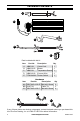
AA
AA
CC
INSTALLATION
-
CRHQD250T, Q SERIES, B23 SERIES,
PCSD25RT, CRHSD25RT AND FBD400 SERIES
WARNING: Before installing
the blower, be certain to turn o
the unit, and allow time for unit
to cool down.
1. Remove screws securing blower access
panel to back of stove (see Figure 18).
Place screws in a safe location.
Blower
Temperature
Sensor
Power Cord
Figure 18 - Removing Blower Access Panel
Figure 19 - Attaching Blower to Blower
Access Panel
Figure 20 - Attaching Power Cord to
Blower Access Panel
Figure 21 - Attaching Temperature
Sensor to Firebox
Figure 22 - Feeding Wire Harness
2. Attach blower to the inside of the blower
access panel with 4) M4.2X8 screws (CC)
(see Figure 19).
3. Attach the power cord to the outside of
the blower access panel with 3) M4.2X8
screws (AA) (see Figure 20).
4. Attach the temperature sensor to the back
of the rebox with 2) M4.2X8 screws (AA)
(see Figure 21).
5. Insert wires marked with AUTO, OFF and
MAN into wire slot in the right corner of
the stove body. Feed the wires down and
as close to the bottom of the stove as
possible (see Figure 22).
PCSD25RT Only