
Use And Care Manual


www.usaprocom.com
200070-01E
6
T1
T2
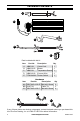
Figure 9 - Installing Temperature Sensor
Figure 10 - Feeding Wire Harness
Figure 11 - Temperature Sensor Wires
9. Attach temperature sensor to the back of
the rebox with 2) M4.2X8 screws (AA)
(see Figure 9).
10. Insert the wires marked with AUTO, OFF
and MAN into wire slot in the right corner.
Feed them as close to the bottom of the
rebox as possible (see Figure 10).
MAN
OFF
AUTO
11. Connect two black and yellow wires (fe-
male ports) marked T1 and T2 with the
two male ports on the temperature sensor
(see Figure 11).
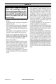
INSTALLATION
-
ED SERIES
Figure 7 - Connecting P2 Wires
Figure 6 - Connecting P1 Wires
Figure 8 - Securing Blower Wires
P2
6. Insert the female port, which is on the
white power supply wire (marked with P1),
into the corresponding male port (marked
with P1), (see Figure 6).
7. Insert the male port, which is on the black
power supply wire (marked with P2), into
the corresponding female port (marked
with P2), (see Figure 7).
P1
8. Bundle the wiring with the cable tie (BB).
Attach cable tie to the top panel through
the hole as shown in Figure 8. This is to
avoid any heat damage to the insulation
board.
BB
Temperature
Sensor
Install End of Cable
Tie Through Hole
AA
Temperature
Sensor