
Use And Care Manual


www.usaprocom.com
200070-01E
10
AA
INSTALLATION
-
CRHQD250T, Q SERIES, B23 SERIES,
PCSD25RT, CRHSD25RT AND FBD400 SERIES
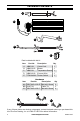
6. Connect two black and yellow wires (fe-
male ports) marked T1 and T2 with the
two male ports on the temperature sensor
(see Figure 23).
Figure 23 - Temperature Sensor Wires
T1
T2
Temperature
Sensor
Grounding
Tab
Grounding
Tab
7. Insert the female port, which is on the
white power supply wire (marked with P1),
into the corresponding male port (marked
with P1) (see Figure 24).
Figure 25 - Connecting P2 Wires
Figure 24 - Connecting P1 Wires
P2
P1
8. Insert the male port, which is on the black
power supply wire (marked with P2), into
the corresponding female port (marked
with P2) (see Figure 25).
9. Insert the blower connector (male port)
into the female port on the wire connector.
This protects the jacket in the replace
(see Figure 26).
Figure 26 - Connecting Blower Wire to
Wire Connector
Figure 27 - Attach Grounding Wire
Figure 28 - Adjusting Grounding Tab
10. Attach the grounding terminal to the tab
on the right side of the blower access hole
with 1) M4.2X8 screw (AA) (see Figure
27).
11. Push grounding tab inwards (approxi-
mately 60 degrees) (see Figure 28).
Male Port
Female
Port