QEB100 BLOWER ACCESSORY INSTALLATION INSTRUCTIONS Spanish/Español Page 17 WARNING: ELECTRICAL GROUNDING INSTRUCTIONS This appliance is equipped with a three-prong (grounding) plug for your protection against shock hazard and should be plugged directly into a properly grounded three-prong receptacle. Questions, problems, missing parts? Before returning to your retailer, call our customer service department at 1-866-573-0674, 7:30 am - 4:15 pm CST, Monday through Friday or email customerservice@usaprocom.
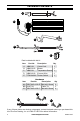
PACKAGE CONTENTS A B C D E Parts included with this kit Item A B C D E Part No. XB001-01 XB002-01Q XB003-01 XB004-01Q PF06-0400-A Description Qty Power Cord 1 Blower 1 Temperature Sensor 1 Connect Wire 1 Rocker Switch 1 Hardware Item Part No. AA GB/T 845-4.2*9.5F BB VL057-01 CC GB/T 845-4.2*9.5 Description Qty M4.2x9.5 Screw 6 Cable Tie 2 M4.2x9.5 Screw 4 AA BB CC If any of these pieces are missing or damaged, contact the dealer where you purchased this kit or ProCom Heating, Inc.
SAFETY IMPORTANT: Read all instructions and warnings carefully before starting installation. Failure to follow these instructions may result in a possible electric shock, fire hazard and will void the warranty. • Read all instructions before using this appliance. • If possible always unplug this appliance when not in use. • Do not operate any heater with a damaged cord or plug or after the appliance malfunctions, has been dropped or damaged in any manner.
PREPARATION Tools Required • Phillips Screwdriver • Wire Cutter This blower contains assembly instructions for ED series. For the CRHQD250T, CRHSD25RT, BD23 series, Q stove, PCSD25RT series and FBD400 series see page 8 - 13. BLOWER INSTALLATION ED SERIES Protection Tab Install Power Cord and Grounding Terminal Install Blower Install Temperature Sensor to Back of Firebox after Removing Top Cover Top Cover Install Rocker Switch 4 www.usaprocom.
INSTALLATION - ED SERIES WARNING: Before installing the blower, be certain to turn off the unit, and allow time for unit to cool down. 4. Attach the grounding terminal to top cover with 1) M4.2X8 screw (AA). Refer to wiring diagram, page 15. Be sure to insert the gasket between the protection tab and the grounding terminal (see Figure 4). AA 1. Unscrew and remove top cover of the fireplace (see Figure 1).
INSTALLATION - ED SERIES 6. Insert the female port, which is on the white power supply wire (marked with P1), into the corresponding male port (marked with P1), (see Figure 6). 9. Attach temperature sensor to the back of the firebox with 2) M4.2X8 screws (AA) (see Figure 9). P1 Temperature Sensor AA Figure 6 - Connecting P1 Wires 7. Insert the male port, which is on the black power supply wire (marked with P2), into the corresponding female port (marked with P2), (see Figure 7).
INSTALLATION - ED SERIES 12. Remove 2 screws securing grill to stove front. Carefully set grill aside (see Figure 12). 16. Connect the AUTO, OFF, MAN wires to the three corresponding male tabs on the rocker switch (see Figure 15). AUTO Rocker Switch Figure 12 - Removing Grill from Fireplace 13. Remove logs and carefully set aside. Note log placement before removing. 14. Remove 2 screws securing control panel. Pull the control panel out without disconnecting the ignitor wire (see Figure 13).
INSTALLATION Install Blower CRHQD250T and Q Series Install Wiring and Install Temperature Grounding Terminal Sensor Install Rocker Switch BD23 Series PCSD25RT and CRHSD25RT Install Temperature Sensor Install Install Wiring and Blower Grounding Terminal Install Rocker Switch Install Rocker Switch FBD400 Series Install Blower Install Temperature Sensor Install Wiring and Grounding Terminal Install Rocker Switch 8 www.usaprocom.
INSTALLATION - CRHQD250T, Q SERIES, B23 SERIES, PCSD25RT, CRHSD25RT AND FBD400 SERIES WARNING: Before installing the blower, be certain to turn off the unit, and allow time for unit to cool down. 4. Attach the temperature sensor to the back of the firebox with 2) M4.2X8 screws (AA) (see Figure 21). 1. Remove screws securing blower access panel to back of stove (see Figure 18). Place screws in a safe location. Temperature Sensor AA Figure 18 - Removing Blower Access Panel 2.
INSTALLATION - CRHQD250T, Q SERIES, B23 SERIES, PCSD25RT, CRHSD25RT AND FBD400 SERIES 6. Connect two black and yellow wires (female ports) marked T1 and T2 with the two male ports on the temperature sensor (see Figure 23). 9. Insert the blower connector (male port) into the female port on the wire connector. This protects the jacket in the fireplace (see Figure 26). Male Port T1 T2 Temperature Sensor Female Port Figure 23 - Temperature Sensor Wires 7.
INSTALLATION - CRHQD250T, Q SERIES, B23 SERIES, PCSD25RT, CRHSD25RT AND FBD400 SERIES 12. Bundle the wiring with the cable tie (see Figure 29). Attach cable tie to the stove through the hole as shown in Figure 29. This is to avoid any heat damage. Actual heater may vary from illustration. BD23 Series models have the cable tie hole in the top panel. For all other models, the hole will be to the right of the blower access opening. 13. CRHQD250T and Q Series Remove 2 screws securing grill to stove front.
INSTALLATION - CRHQD250T, Q SERIES, B23 SERIES, PCSD25RT, CRHSD25RT AND FBD400 SERIES 15. CRHQD250T, Q Series and BD32 Series Remove screws securing front log bracket and control panel (see Figure 31a). CRHSD25RT and PCSD25RT Remove screws securing control panel (see Figure 31b). FBD400 Series Remove screws securing control panel (see Figure 31c). 16. BD23 Series Remove screws securing control panel door (see Figure 32).
INSTALLATION - CRHQD250T, Q SERIES, B23 SERIES, PCSD25RT, CRHSD25RT AND FBD400 SERIES 19. Push the rocker switch into the control panel (see Figure 35). 20. Reattach the control panel and log bracket (if applicable) with screws removed in step 15 (see Figure 31, page 12). 21. Reinstall logs according to original layout. Refer to owner's manual for log placement. 22. CRHQD250T and Q Series Replace grill with 2 screws removed previously (see Figure 30, page 11). For other models, close stove door. 23.
GROUNDING INSTRUCTIONS This heater is for use on 120 volts. The cord has a plug as shown at A. An adapter as shown at C is available for connecting three-blade grounding-type plugs to two-slot receptacles. The green grounding lug extending from the adapter must be connected to a permanent ground such as a properly grounded outlet box. The adapter should not be used if a three-slot grounded receptacle is available.
ELECTRICAL WIRING DIAGRAM Any electrical re-wiring of this appliance must be done by a qualified electrician. This wiring must be done in accordance with local codes and/or in Canada with the current CSA C22.1 Canadian Electrical Code, and for US installations, the National Electrical Code ANSI/ NFPA NO 70. WARNING: If repairing or replacing any electrical component or wiring, the original wire routing, color coding and securing locations must be followed.
WARRANTY KEEP THIS WARRANTY Model ________________________________ Serial No. _____________________________ Date Purchased ________________________ Keep receipt for warranty verification. REGISTER YOUR PRODUCT AT WWW.USAPROCOM.COM IMPORTANT: We urge you to register your product within 10 days of date of installation, complete with entire serial number which can be found on the rating plate. Please fill out the warranty information above for your personal records. Retain this manual for future reference.