MOBILE CLEANING UNIT Operating Instructions (ENG) MODELS: PEAK GTX 1.001-132.0 Read instructions before operating the machine.
Left intentionally blank
Machine Data Log / Overview Welcome…and congratulations on the purchase of your Mobile Cleaning Unit. This instruction manual is a guide for operating and servicing your unit. Read this manual completely before installing or operating this unit. This unit offers you personal convenience. All of your instrumentation and controls have been positioned to give you easy access for operation and daily maintenance. Proper operation and service are essential to the efficient functioning of this unit.
Table of Contents Machine Data Log / Overview . . . . . . . . . . . . . . . . . 1 Table of Contents . . . . . . . . . . . . . . . . . . . . . . . . . . . 2 Receiving Your Unit . . . . . . . . . . . . . . . . . . . . . . . . . 4 Acceptance of Shipment . . . . . . . . . . . . . . . . . . . . . 4 Equipment List . . . . . . . . . . . . . . . . . . . . . . . . . . . . . 4 How to Use This Manual . . . . . . . . . . . . . . . . . . . . . 5 Safety IMPORTANT SAFETY INSTRUCTIONS. . . . . . . . .
Table of Contents Parts Options Frame . . . . . . . . . . . . . . . . . . . . . . . . . . . . . . . . . . Side Panel. . . . . . . . . . . . . . . . . . . . . . . . . . . . . . . Chemical Panel. . . . . . . . . . . . . . . . . . . . . . . . . . . Control Panel . . . . . . . . . . . . . . . . . . . . . . . . . . . . Engine. . . . . . . . . . . . . . . . . . . . . . . . . . . . . . . . . . Engine. . . . . . . . . . . . . . . . . . . . . . . . . . . . . . . . . . Vacuum Pump . . . . . . . . . . . . . . . . .
Receiving Your Unit Acceptance of Shipment Equipment List Every part of your cleaning unit was carefully checked, tested, and inspected before it left our manufacturing plant. Upon receiving the unit, make the following acceptance check: 1. Console. 1. The unit should not show any outward signs of damage. If damaged, notify the common carrier immediately. 4. 100 ft. of 2" vacuum hose. 2. Check your equipment and packing list.
How to Use This Manual This manual contains the following sections: • • • • • • How to Use This Manual Safety Installation Operations Maintenance & Service Parts List The INSTALLATION section contains information on how to properly install the unit in your vehicle. The OPERATIONS section is to familiarize the operator with the operation and function of the machine. The HOW TO USE THIS MANUAL section will tell you how to find important information for ordering correct repair parts.
Safety IMPORTANT SAFETY INSTRUCTIONS When using this machine, basic precaution must always be followed, including the following: READ ALL INSTRUCTIONS BEFORE USING THIS MACHINE. These symbols mean WARNING or CAUTION. Failure to follow warnings and cautions could result in fatality, personal injury to yourself and/or others, or property damage. Follow these instructions carefully! Read the operator's manual before installing or starting this unit.
Safety DO NOT leave the vehicle engine running while operating this unit. Dangerous Acid, Explosive Gases! Batteries contain sulfuric acid. To prevent acid burns, avoid contact with skin, eyes and clothing. Batteries produce explosive hydrogen gas while being charged. To prevent a fire or explosion, charge batteries only in well ventilated areas. Keep sparks, open flames, and other sources of ignition away from the battery at all times. Keep batteries out of the reach of children.
Safety The following symbols are used throughout this guide as indicated in their descriptions: Hazard Intensity Level There are three levels of hazard intensity identified by signal words - WARNING and CAUTION and FOR SAFETY. The level of hazard intensity is determined by the following definitions: WARNING - Hazards or unsafe practices which COULD result in severe personal injury or death. CAUTION - Hazards or unsafe practices which could result in minor personal injury or product or property damage.
Safety Safety Labels The following WARNING LABELS are found on your cleaning unit. These labels point out important Warnings and Cautions which should be followed at all times. Failure to follow warnings and cautions could result in fatality, personal injury to yourself and/or others, or property damage. Follow these instructions carefully! DO NOT remove these labels. NOTE: If at any time the labels become illegible, promptly replace them.
Installation Dealer Responsibility Your distributor from whom you purchased this mobile cleaning unit is responsible for correct installation of this machine. The dealer is also responsible for initial training of your operators and maintenance personnel in proper operation and maintenance of this unit. Vehicle Requirements 1. The unit should NOT be mounted in any motor vehicle of less than 3/4 ton capacity. DO NOT exceed the vehicle’s axle weight limit.
Installation Lifting Unit Onto Vehicle Bolting Down Unit And Waste Tank Since console weighs approximately 794 lbs. pounds, we recommend using a forklift to lift unit onto vehicle. Position forks under unit from front and make CERTAIN that forks are spread to insert into frame slots. NOTE: When positioning waste tank with respect to console, hook up the vacuum hose to waste tank. This will ensure that waste tank is positioned correctly.
Installation Layout with 60 Gallon Waste Tank BACK OF DRIVERS SEAT IN REAR MOST POSITION. 3781" 1 2" 2X 121" 3 2X 616 " 17 8" 6X Ø3 8" 11 716 " 2X 123 8" 57 8" 2X 17 8" 334" MIN. 6X Ø3 8" 6713 16" 2X 195 8" 2X 3641" 11 16" 293 8" TOP VIEW ENSURE THAT VAC INLETS ON CONSOLE AND WASTE TANK ARE ALIGNED.
Installation Layout with 100 Gallon Waste Tank 1 2" BACK OF DRIVERS SEAT IN REAR MOST POSITION. 4981" 2X 121" 3 2X 616 " 6X Ø38" 1378" 2X 1238" 578" 11 716 " 334" MIN. 6X Ø38" 2X 178" 2X 1958" 6713 16" 2X 3641" 11 16" TOP VIEW 2938" ENSURE THAT VAC INLETS ON CONSOLE AND WASTE TANK ARE ALIGNED.
Installation Waste Tank To Console Connection NOTE: Before connecting any hoses to the waste tanks, make certain the hose clamps are on each hose. 1. Connect the section of 2-7/8" I.D. internal vac hose between the 2-7/8" dia. vac outlet tube on the waste tank and the vacuum pump relief valve on the console. It may be necessary to cut this hose to fit. Tighten the hose clamps. 2. Connect the 2" I.D. waste removal hose to the 2" dia. tube at the bottom corner of the waste tank. Cut to desired length.
Installation Van Bulkhead Installation 1. Select a location on the vehicle floor to drill the hole for the bulkhead adapter. This location should be situated in a position that eliminates the possibility of fuel line contact by either the operator(s) or accessories during the working hours or maintenance periods. Make certain that the supplied hoses will reach the location and work with the configuration you choose. 2. Drill a 5/8" (.
Installation Fuel Supply & Return Line Installation (Underneath Van) 1. Attach the 1/8 NPT x 5/16 Hosebarb 90 degree elbow to the bulkhead adapter underneath the van to be used for the fuel supply line. 2. Cut to length the 6' piece of 5/16" 50 PSI fuel hose used for the supply line from: a. Bulkhead adapter to the outlet side of the bypass fuel filter. b. Inlet side of the bypass fuel filter to the discharge side of the fuel pump. c. Inlet side of the fuel pump to the outlet side of the inline fuel filter.
Installation Battery Connection Dangerous Acid, Explosive Gases! Batteries contain sulfuric acid. To prevent acid burns, avoid contact with skin, eyes, and clothing. Batteries produce explosive hydrogen gas while being charged. To prevent a fire or explosion, charge batteries only in well-ventilated areas. Keep sparks, open flames, and other sources of ignition away from the battery at all times. Keep batteries out of the reach of children. Remove all jewelry when servicing batteries.
Installation Initial Operational Settings Engine NOTE: Due to temperature and altitude changes, the optimal settings for each truckmount must be adjusted after installation. Failure to make these adjustments may lead to poor unit performance and premature component failure. Vacuum Pump The maximum vacuum pressure obtainable at full throttle should be 13"Hg. If the unit is drawing a stronger vacuum (at full sealed suction) than 13" Hg, adjust the vacuum relief spring to 13" Hg.
Operations Technical Specifications ITEM Engine speed Solution pump rpm Vacuum pump rpm Water flow rate Solution pump pressure (low pressure) Vacuum relief valve Waste tank capacity Console weight Console weight (with 60 gallon waste tank & waste tank accessories) Console weight (with 100 gallon waste tank & waste tank accessories) TORQUE VALUES Engine hub Vacuum pump hub Front engine pulley Solution pump clutch shaft bolt DIMENSION/CAPACITY 2850 rpm (high speed) Water Pump ON 1200 rpm (idle speed) Water P
Operations Fuel Requirements Altitude Requirements Use unleaded gasoline ONLY. DO NOT use any gasoline additives. We recommend the use of clean, fresh, unleaded gasoline intended for automotive use. High octane gasoline should NOT be used with the engine on this unit. These engines are NOT designed to use E-85 or Flex Fuels. Engines perform differently with increases/decreases in altitude. Be sure to check engine speeds during initial installation. See engine speeds in Technical Specifications section.
Operations Water Requirements Hard water deposits will adversely affect the plumbing and heat exchange systems on this unit. The map below will give you an idea of where areas of high water hardness may occur. However, any water supply obtained from a well is almost always hard water and a water softener will be needed to protect your equipment. NOTE: Equipment malfunction or component failure caused by hard water scaling is NOT covered under the warranty.
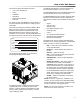
Operations Components 1 2 3 4 5 6 7 8 26 25 9 24 10 11 23 12 13 14 22 15 21 20 19 22 18 17 86325860 PEAK GTX PROCHEM 16
Operations Components 9. Solution Pump Switch 1. Solution Temp Control Valve This valve allows the operator to control the solution temperature by bypassing hot water to the waste tank, for low temperature cleaning such as upholstery. Turning the valve counter clockwise opens the valve. Turning clockwise closes the valve and has the effect of stopping water from bypassing. 2. Vacuum Gauge This gauge indicates in inches of mercury how much vacuum the system is producing at any given time. 10.
Operations 22. Solution Pressure Regulator 15. Vacuum Inlets The vacuum inlets serve as connecting points for vacuum hoses. 16. Exhaust Exhaust fumes contain carbon monoxide which is an odorless and deadly poison that can cause severe injury or fatality. DO NOT run this unit in an enclosed area. DO NOT operate this unit where the exhaust may enter any building doorway, window, vent, or opening of any type 17.
Operations Vacuum System The engine turning a vacuum pump generates vacuum. The air is channeled in one side of the vacuum pump, compressed and discharged on the opposite side, creating airflow. The movement of air is used to do the work necessary for the extraction process. A vacuum nozzle applied to the carpet surface removes moisture, dirt and spent chemicals. These elements are conveyed back to a separating tank utilizing hoses and the force of air.
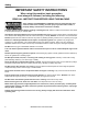
Operations Water Pumping and Heat Transfer System Cold water enters the console through the water inlet. When the water box is full the valve will automatically shut off. Water then flows from the water box, through the strainer, into the solution pump. The water is pumped to the pressure regulator manifold, which provides and maintains the desired pressure setting. The pressure regulator manifold includes a pulse hose which helps reduce pressure spikes from the pump.
Operations = COLD WATER = WARM WATER WASTE TANK = HOT WATER = NO WATER VACUUM EXHAUST HEAT EXCHANGERS THERMO RELIEF WATER BOX HELI-COIL ENGINE COOLANT HEAT EXCHANGER ENGINE SOLUTION PUMP ENGINE THERMOSTAT RADIATOR TO PRESSURE GAUGE TEMPERATURE CONTROL BYPASS PULSE HOSE MANIFOLD CHEMICAL INJECTION WATER INLET PRESSURE REGULATOR SOLUTION OUTLET MANIFOLD CHEMICAL CHECK VALVE 86325860 PEAK GTX PROCHEM SOLUTION OUTLETS SOLUTION SCREEN 27
Operations Chemical Injection System The chemical injection system is unique in that it utilizes the pressure spikes generated by the highpressure solution pump to move chemical into the main solution stream. The high pressure spikes move the diaphragm in the chemical pulse pump forcing small amounts of liquid chemical to be moved in a single direction of flow with the aid of two check valves. The chemical is drawn from the container, and through the flow meter, which indicates rate of flow.
Operations Pre-Run Inspection / Setup High Pressure Solution Hose NOTE: Operation of this unit is simple. However, only trained personnel should proceed. Operate this unit and equipment only in a well-ventilated area. Exhaust fumes contain carbon monoxide which is an odorless and deadly poison that can cause severe injury or fatality. DO NOT operate this unit where the exhaust may enter any building doorway, window, vent, or opening of any type.
Operations Priming the Chemical Pump 1. Fill chemical container and inspect chemical strainer. 2. Insert chemical inlet tubing into chemical container. NEVER dispose of waste in storm drains, waterways, or on ground areas. Always dispose of waste in accordance with Local, State, and Federal laws. 3. Pull out engine choke, turn solution pump switch to override, and turn ignition key to start. Waste Pumpout (Optional) 4. Push in engine choke after engine has started. 5. Set throttle to idle position. 6.
Operations Upholstery Cleaning De-flooding operations Upholstery tool, (See Options Section) De-flooding operations involve removal of water from carpet and flooring. This differs from normal cleaning operations in that no water or solution is required. An automatic waste pump-out is highly recommended for all de-flooding operations due to the large amount of water removal often required. 1.
Operations Winterizing Your Unit 1. Shut off the water supply. Disconnect the water inlet hose from the front of your console. 2. Connect all solution pressure hoses and tools that may have water in them. 3. Start the unit and turn solution pump on. Open the tool valve until water pressure drops and water stops flowing. 4. Turn off the solution pump. Fill the water box with approximately two gallons of 100% glycol base anti-freeze. 5. Turn the solution pump switch ON. 6.
Operations Removing Anti-Freeze From the Unit 1. Connect one end of the winterizing loop hose to the bottom solution outlet connection. Place the other end of the loop hose, without the attachment, into an approved container. 2. Start the unit. Allow the anti-freeze to flow into the container until flow stops. 3. Fill the water box with fresh water and repeat step #2. 4. Connect the water inlet hose to the water inlet connection on the console. Turn the water supply on. 5.
Maintenance Service Schedule Engine Engine Daily Daily Vacuum Pump Daily Solution Pump Chemical Inlet Tube Strainer Vacuum Inlet Filter (In Waste Tank) Vacuum Hoses Automatic Waste Pump Vacuum Pump Water Box Float Valve Solution Pump Inlet Strainer Battery Solution Outlet Screen Pressure Regulator Pressure Regulator Solution Pressure Hoses Engine Engine Engine Battery Float Valve Seal Engine Engine Fuel Pump Engine Chemical Valves 34 Daily Daily Daily Daily Daily Weekly* Weekly Weekly* Weekly* Weekly*
Maintenance Service Schedule Vacuum Exhaust Heat Exchanger Solution Pump Pulley Set Screws & Hub Cap Screws, Solution Pump Clutch Shaft Bolt Drive Pulley Drive Pulley Drive Belts Drive Belts Chemical Pump & Check Valves 500 hrs 500 hrs Inspect cores and remove debris. Change oil** 500 hrs Check for proper torque values.
Maintenance Key Checkpoints Heat Exchanger System Maintenance Note: Initiation of a planned preventative maintenance program will assure that your unit has optimum performance, a long operating life, and a minimal amount of "down" time. The heat exchange system in your unit transfers energy between the engine’s exhaust and blower discharge air to the solution supply system.
Maintenance DO NOT service this unit while it is running. The highspeed mechanical parts as well as high temperature components may result in severe injury, severed limbs, or fatality. NOTE: Use the hour meter as a guide for coordinating the maintenance schedule. Engine (Refer to engine manufacturer's manual for specific maintenance instructions) 1. Check the engine oil level daily, when in use. Make certain that proper oil level is maintained. NEVER overfill. 2.
Maintenance Vacuum Pump Refer to the Vacuum Pump Operation and Service Manual (P/N 86269820) for specific instructions. Lubrication: We recommend that you use AEON PDXD Synthetic Blower Lubricant in both ends of the vacuum pump for all operating temperatures. AEON PD-XD is formulated especially for positive displacement blower service to provide maximum blower protection at any temperature. One filling of AEON PDXD will last many times longer than a premium mineral oil.
Maintenance Solution Pump Vacuum Relief Valve Refer to the Solution Pump Operation and Service Manual for specific instructions (P/N 86269900). While the unit is running at full RPM, block the air flow at the vacuum inlet connection and read the vacuum gauge. If adjustment is required, shut the unit down and adjust the vacuum relief valve locking nut tension. Start your unit and read the vacuum gauge. Repeat this process until the relief valve opens at 13" Hg. 1.
Maintenance Solution Pump Drive Belt Waste Tank Strainer Basket To tighten the solution pump belt: The strainer basket located inside the waste tank should be removed and cleaned whenever it is full of debris. This should be done at the end of each job. 1. Loosen the nuts which hold the solution pump mount to base. 2. Adjust the position of the belt tension adjusting bolt until the proper belt tension is achieved. (1/2" deflection in the center of the belt, halfway between the pulleys). 3.
Maintenance Chemical Pump Optional Waste Pump-Out Rebuild the chemical pump every 500 hours. This involves changing the diaphragm, plastic disk and check valves. At the end of each work day, make certain that you remove any debris or sediment which may be inside the waste pump by pumping fresh water through the pump. For the procedure, see the “General Service Adjustments” section in this manual for details. Engine Coolant Replacement NOTE: Inspect chemical inlet tube strainer daily.
Maintenance General Service Adjustments NOTE: Improper seating of the check valve poppet, damaged spring or o-rings will cause poor operation of the chemical system. The high-speed mechanical parts as well as high temperature components may result in severe injury, severed limbs, or fatality. Engine Speed 1. This unit uses a governor to set and maintain engine speed. The engine speed is adjusted by pulling the throttle out to maximum travel for high speed operation.
Maintenance Packing Nut Adjustments For Chemical Valves Examine the packing nut on all chemical valves for proper tension every 200 hours. When turning the knob, there should be a small amount of resistance. If not, slightly tighten the packing nut. DO NOT over tighten. Keeping the valve packings properly adjusted will eliminate possible leakage from the valve stem and add to overall valve life. DO NOT loosen the adjusting body (cap) all the way (counterclockwise) or remove it while the unit is running.
Maintenance Troubleshooting PROBLEM CAUSE Water supply is turned off or the float valve is stuck or improperly adjusted. Solution pump inlet supply line is plugged or drawing air. Improper engine speed Loss of solution pump pressure. Pressure regulator o-ring is dry. With the cleaning tool Pressure regulator has worn o-ring open, the solution pressure gauge reads Pressure regulator is dirty, stuck open, below the normal or improperly adjusted. operating pressure. Low pump volume.
Maintenance PROBLEM CAUSE Vacuum obstruction Vacuum gauge is giving an improper reading. Vacuum hose(s) is damaged, causing a suction leak. Waste tank gaskets not sealing properly, not positioned properly Plugged vacuum hose or vacuum plumbing Loss of vacuum between vacuum inlet and strainer basket. While cleaning, Waste tank filter or strainer basket is the vacuum is plugged. not up to specification. Engine Loose vacuum pump drive belts. RPM is normal.
Maintenance PROBLEM Chemical flow meter indicates flow with the tool valve closed Solution pump does not engage Engine will not start. The engine does not turn over Starter turns over engine, but will not start 46 CAUSE SOLUTION Tighten fittings. Re-apply thread sealant where External leak in chemical piping required. If any fittings are damaged, replace. Close the chemical valve on the instrument panel.
Maintenance PROBLEM Engine stops running. While doing normal cleaning, the engine stops running Excessive heating Heat exchanger leaks. NOTE: The heat exchanger will produce water condensation discharge at times during normal operation. DO NOT confuse this with a leak. CAUSE Engine is out of gasoline Waste tank is full SOLUTION Add gasoline to the fuel tank. Empty waste tank.
Notes: 48 86325860 PEAK GTX PROCHEM
Parts PARTS 86325860 PEAK GTX PROCHEM 49
Frame 10 11 14 15 18 19 8 1 1 8 1 6 6 17 3 1 3 1 2 1 6 7 2 1 8 6 16 5 9 5 9 9 4 9 4 20 22 50 6 13 21 86325860 PEAK GTX PROCHEM 12
Frame REF PART NO. QTY 1 2 3 4 5 6 7 8 9 10 11 12 13 14 15 16 17 18 19 20 21 22 86270330 86177090 86005680 86005770 86274000 86274750 86233390 86010780 86279510 86282840 86282850 86341640 86315490 86323010 86323350 86323390 86323900 86349170 86349160 86177430 86010790 86006920 12 2 2 4 4 10 1 8 8 2 2 1 2 1 1 1 1 2 2 1 1 1 DESCRIPTION FLATWASHER, 1/4 CLAMP, CABLE 1/2I.D.
Frame 1 2 11 2 1 2 15 5 9 3 8 TO WATER BOX 7 14 4 6 2 10 13 52 9 9 12 86325860 PEAK GTX PROCHEM 2
Frame REF PART NO. QTY 1 2 3 4 5 6 7 8 9 10 11 12 13 14 15 86273330 86270330 86177060 86188210 86177640 86181360 86179710 86178700 86005680 86275460 86233390 86277730 86323360 86323370 86323480 3 10 1 1 1 1 1 1 7 1 1 4 1 1 1 DESCRIPTION SERIAL NO. FROM NOTES SCR, CAP 1/4-20 X 2.
Frame 19 21 22 18 13 1 11 17 3 2 3 8 10 23 13 3 7 16 15 2 3 9 16 15 4 12 6 14 54 86325860 PEAK GTX PROCHEM 20 5
Frame REF PART NO. QTY 1 2 3 4 5 6 7 8 9 10 11 12 13 14 15 16 17 18 19 20 21 22 23 86273180 86273330 86270330 86177040 86161800 86176170 86005680 86270990 86271970 86279340 86010780 86057150 86189050 86179620 86191800 86315490 86322980 86322990 86323050 86325280 86325290 86326000 86360670 2 3 14 1 4 1 9 4 4 4 2 2 2 1 16 3 1 1 1 1 1 1 2 DESCRIPTION SERIAL NO. FROM NOTES SCR, 1/4-20 X 1" HXHD GRD8 SCR, CAP 1/4-20 X 2.
Side Panel 1 2 56 86325860 PEAK GTX PROCHEM
Side Panel REF PART NO. QTY 1 2 86325380 86180700 1 1 DESCRIPTION SERIAL NO.
Chemical Panel 14 13 2 5 1 10 15 4 6 8 11 12 3 9 7 16 17 58 86325860 PEAK GTX PROCHEM
Chemical Panel REF PART NO. QTY 1 2 3 4 5 6 7 8 9 10 11 12 13 14 15 16 17 86273180 86270330 86176990 86188000 86194160 86177660 86181300 86195050 86181170 86247720 86274290 86279470 86189050 86195160 86297070 86324090 86324460 2 2 2 1 1 4 2 1 1 2 2 2 2 1 1 1 1 DESCRIPTION SERIAL NO.
Control Panel 29 16 26 14 23 13 28 7 22 15 9 10 25 9 1 2 12 30 3 27 18 24 5 31 11 19 21 7 6 4 10 8 20 60 86325860 PEAK GTX PROCHEM 17
Control Panel REF PART NO.
Engine 21 22 16 9 17 19 3 20 18 8 1 11 10 12 6 5 2 7 13 14 14 4 62 15 86325860 PEAK GTX PROCHEM
Engine REF PART NO. QTY DESCRIPTION 1 2 3 4 5 6 7 8 9 10 11 12 13 14 15 16 17 18 19 20 86273440 86182290 86136310 86005770 86274000 86136640 86275190 86006820 86277890 86279130 86010740 86137310 86010790 86279510 86051510 86349040 86177130 86323820 86182730 86136280 4 1 1 6 2 1 2 4 1 4 1 1 2 14 1 1 1 1 2 4 SCR, MACH 5/16-18 X 1" GR8 GSKT, EXH, KUB, D902/WG972 NUT, M5 HEX NUT, 3/8-16 HEX NYLOCK SCR, 3/8-16 X 3 HHCS GR5 SCR, M8-1.25 X 20 HHMS PLTD SCR, 3/8-16 X 1.25 HHCS SS SCREW 3/8-16 X 2.
Engine 21 SUPPLIED WITH ENGINE 16 18 TO LOWER FITTING ON HELICOIL 4 14 18 6 10 9 18 20 17 23 18 2 15 5 TO TOP FITTING ON HELICOIL 22 3 13 8 19 7 64 12 11 86325860 PEAK GTX PROCHEM 1
Engine REF PART NO.
Vacuum Pump TO WASTE TANK 4 20 1 6 7 8 5 17 12 18 23 9 19 14 3 22 25 16 17 13 11 16 21 10 15 4 24 TO SILENCER 66 86325860 PEAK GTX PROCHEM 2
Vacuum Pump REF PART NO.
Solution Pump 33 34 35 30 14 2 31 6 32 3 24 FROM WATER BOX 20 18 17 FROM FLOWMETER 16 25 5 22 15 11 7 8 23 19 36 43 37 12 38 1 28 9 10 29 42 41 39 40 27 13 38 26 37 21 4 44 68 86325860 PEAK GTX PROCHEM
Solution Pump REF PART NO. QTY DESCRIPTION 1 2 3 4 5 86326970 86279820 86355300 86183470 86191440 1 1 1 1 1 BRKT, WTR PMP MTG WSHR, .328 ID X 1.00 OD X .
Solution Pump 5 1 14 2 13 6 10 3 9 4 5 11 8 7 12 15 12 7 70 15 86325860 PEAK GTX PROCHEM
Solution Pump REF PART NO.
Vacuum / Exhaust Heat Exchanger and Silencer 14 10 1 16 2 11 15 5 6 9 21 7 21 19 TO WATER BOX 24 3 4 17 13 FROM REGULATOR 21 8 23 18 21 72 12 86325860 PEAK GTX PROCHEM 7 21
Vacuum / Exhaust Heat Exchanger and Silencer REF PART NO.
Helicoil Heat Exchanger 1 10 2 FROM THERMOSTAT ADAPTER ON ENGINE 11 TO HEAT EXCHANGER 9 6 8 3 4 5 7 6 4 TO PRESSURE REGULATOR 3 TO ENGINE "Y" ADAPTER 74 86325860 PEAK GTX PROCHEM
Helicoil Heat Exchanger REF PART NO. QTY 1 2 3 4 5 6 7 8 9 10 11 86177560 86342100 86177310 86181420 86180260 86180430 86180000 86010790 86279510 86006740 86233410 1 1 2 2 1 2 1 2 2 2 1 DESCRIPTION SERIAL NO. FROM NOTES COCK, DRN 1/4P X 1/4 HOSE ELL ASSEMBLY, HELICOIL CLMP, HOSE #16 1-1/2 MIN 1-3/4 FTTG, BRB 3/4PX1H BR ELL, 3/4 ST BR ELL, 3/4PX1/2T BR ELBOW, 3/4" 45 DEG BRASS ST WASHER 3/8 SPLIT LOCK PLTD WASHER, 3/8 FLAT SCREW 3/8-16 X 1" HHCSGR5PLT DL CLAMP, 3/4 DIA CUSHION .
Helicoil Heat Exchanger 6 5 4 1 9 10 14 12 11 3 2 8 5 13 76 86325860 PEAK GTX PROCHEM 7
Helicoil Heat Exchanger DESCRIPTION SERIAL NO. FROM REF PART NO. QTY 1 86344980 1 O-RING, HELICOIL *(1) 2 3 4 5 6 7 8 9 10 11 86342090 86342080 86342070 86278910 86276430 86274010 86271930 86191900 86188980 86182370 1 1 1 24 8 4 12 2 2 2 BRKT, HELICOIL MTG SHELL, FRONT, HELICOIL SHELL, REAR, HELICOIL WASHER, 3/8 X 7/8 FLAT SS SCR, 3/8-16 X 1.75 HHCS SS SCR, 3/8-16 X 2.
Solution Outlet 10 11 4 3 8 17 18 19 7 20 21 22 9 16 1 23 15 2 14 5 13 12 78 6 86325860 PEAK GTX PROCHEM 24
Solution Outlet REF PART NO.
Water Box 1 11 21 5 6 FROM WATER INLET 16 15 5 6 7 7 13 12 8 9 18 17 10 5 6 13 12 REAR 80 86325860 PEAK GTX PROCHEM
Water Box REF PART NO.
Regulator 15 16 2 1 12 10 11 7 2 12 17 4 5 8 TO COPPER CORE 14 3 13 6 OUTER SEAT 9 INNER SEAT CAP STEM SPRINGS BODY 18 PRESSURE REGULATOR DETAIL 82 86325860 PEAK GTX PROCHEM
Regulator REF PART NO. QTY 1 2 3 4 5 6 7 8 9 10 11 12 13 14 15 16 17 18 86273330 86270330 86177060 86190480 86175920 86188130 86180360 86180450 86352940 86274750 86233390 86010780 86184900 86187770 86312330 86313740 86326090 86186040 2 3 1 1 1 1 1 2 1 1 1 3 1 1 1 1 1 1 DESCRIPTION SERIAL NO. FROM NOTES SCR, CAP 1/4-20 X 2.75 HXHD FLATWASHER, 1/4 CLAMP, HOSE, #8 SST PLUG, 1/2 SOCHD BR BUSH, 3/8 X 1/8 BR NIPPLE, 3/8M X 1/4M ELL, 1/8P X 1/4T BR ELL, 3/8P X 1/2T 45 DEG. BR REG.
60 Gallon Waste Tank 15 20 12 7 PART OF 4 8 3 5 11 13 21 9 6 7 16 19 4 10 2 18 TO VACUUM PUMP 1 17 14 84 86325860 PEAK GTX PROCHEM
60 Gallon Waste Tank REF PART NO. QTY 1 2 3 4 5 6 7 8 9 10 11 12 13 14 15 16 17 18 19 20 21 - 98408750 86190530 86180340 86193540 86186860 86043190 86005810 86273020 86273810 86010630 86193870 86202240 86318530 86318560 86320940 86320990 86321040 86323650 86323700 86177010 86350790 86202180 86264850 1 2 3 1 2 1 8 8 8 8 1 8 1 1 1 1 1 1 1 1 1 1 1 DESCRIPTION KIT, WASTE TANK 60G, PC PLUG, 1-1/4 HXHD PVC ELL, 1/4P X 1/4T BR STRNR, WST TNK, RECT, 1.
100 Gallon Waste Tank 15 20 7 PART OF 4 12 8 3 5 11 13 9 6 21 16 7 19 10 4 TO VACUUM PUMP 1 18 2 17 14 86 86325860 PEAK GTX PROCHEM
100 Gallon Waste Tank REF PART NO. QTY 1 2 3 4 5 6 7 8 9 10 11 12 13 14 15 16 17 18 19 20 21 - 98408760 86190530 86180340 86193540 86186860 86043190 86005810 86273020 86273810 86010630 86193870 86202240 86325770 86318560 86325650 86325720 86321040 86323650 86323700 86177010 86350770 86202180 86264850 1 2 3 1 2 1 8 8 8 8 1 8 1 1 1 1 1 1 1 1 1 1 1 DESCRIPTION KIT, WASTE TANK 100 G, PC PLUG, 1-1/4 HXHD PVC ELL, 1/4P X 1/4T BR STRNR, WST TNK, RECT, 1.
Fuel Pump 25 12 TO CONSOLE 13 20 THROUGH VEHICLE FLOOR 20 5 4 24 15 15 14 RETURN TO VEHICLE FUEL SUPPLY MOUNT TO VEHICLE FRAME 16 1 23 FROM VEHICLE FUEL SUPPLY 6 2 16 21 8 8 2 1 7 3 18 88 19 23 9 23 USE AS NEEDED 11 1 16 12 22 86325860 PEAK GTX PROCHEM 10 17
Fuel Pump REF PART NO. QTY 1 2 3 4 5 6 7 8 9 10 11 12 13 14 15 16 17 18 19 20 21 22 23 24 25 - 86010630 86173340 86175970 86176930 86177880 86181300 86191420 86273780 86335230 86335240 86005810 86175850 86175980 86177370 86177390 86177400 86179920 86180960 86181620 86182460 86273810 86282410 86184980 86339630 86179930 86282810 86265730 86273290 14 6 2 1 1 2 1 6 1 1 4 1 1 4 2 7 1 1 1 2 4 1 1 1 1 2 10 4 DESCRIPTION SERIAL NO.
Battery Floor Mount 2 1 10 3 4 5 9 6 7 8 90 86325860 PEAK GTX PROCHEM
Battery Floor Mount REF PART NO. QTY 1 2 3 4 5 6 7 8 9 10 86030550 86273780 86005680 86174580 86012060 86273190 86270330 86010780 86270770 86309890 86011470 1 2 2 1 1 4 8 8 8 1 4 DESCRIPTION KIT,BAT FLR MTG TM SCR, 1/4-20 X 3/4 HHCS SS NP NUT, 1/4-20 HEX NYLOCK BATTERY BOX, BATTERY, MODIFIED SCR, 1/4-20 X 1-1/2 HXHD FLATWASHER, 1/4 WASHER, 1/4 SPLIT LOCK PLTD NUT, 1/4-20 HEX BRKT, BATTERY BOX MTG BOLT, ELEVATOR, 1/4-20 X 1 86325860 PEAK GTX PROCHEM SERIAL NO.
Chemical Jug Floor Mount 5 2 4 1 6 3 92 86325860 PEAK GTX PROCHEM
Chemical Jug Floor Mount REF PART NO. QTY 1 2 3 4 5 6 86298250 86273190 86270770 86270330 86185720 86010780 1 4 4 4 1 4 DESCRIPTION SERIAL NO.
Wiring Diagram 94 86325860 PEAK GTX PROCHEM
WASTE TANK WASTE TANK 86325860 PEAK GTX PROCHEM 86356870 (72") SIDE PANEL 86326810 (120") 86282900 (84-1/2") WASTE TANK WASTE TANK WASTE TANK LOWER CONTROL PANEL TO OVERFLOW 86280090 (42") 86048980 (36") VACUUM BLOWER 86280070 (21") 86183470 (23") 86176990 86181300 86193410 (HOSE, PULSE) 86183750 (24") 86183930 (14-1/2") CHEMICAL JUG SOLUTION OUTLET CONTROL PANEL PRESSURE REGULATOR 86280470 (24") 86184390 (19") HELI-COIL HEAT EXCHANGER 86282430 (30") 86184890 (12") 86312750 (23"
Notes: 96 86325860 PEAK GTX PROCHEM
Options OPTIONS 86325860 PEAK GTX PROCHEM 97
Hose Accessories 1 23 2 3 22 2 7 4 5 10 6 11 12 9 8 14 13 17 18 19 15 21 20 16 98 86325860 PEAK GTX PROCHEM
Hose Accessories REF PART NO. QTY 1 2 3 4 5 6 7 8 9 10 11 12 13 14 15 16 17 18 19 20 21 22 23 86180980 86178640 86184510 86247680 86002450 86005580 86184530 86184520 86182800 86194990 86189240 86189250 86188210 86184570 86179630 86184620 86002450 86184520 86182800 86005580 86184540 86328140 86328150 1 2 1 1 1 1 1 1 2 1 2 2 1 1 1 1 1 1 2 1 1 1 1 DESCRIPTION SERIAL NO.
Exhaust - Optional 5 1 4 3 2 100 86325860 PEAK GTX PROCHEM
Exhaust - Optional REF PART NO. QTY 1 2 3 4 5 - 86177010 86280600 86181110 86192060 86005810 86030440 2 1 1 4 4 1 DESCRIPTION CLAMP, #48 HOSE HOSE, 3" X 17" FLEXABLE FLANGE, VAC EXH DUCT KIT LG SCREW, 1/4-20 X 1-1/4" SST NUT, 1/4-20 HEX NYLOCK SS KIT, EXHAUST 3"ID, SINGLE 86325860 PEAK GTX PROCHEM SERIAL NO.
Heater Core - 3rd - Optional 1 2 3 4 5 102 86325860 PEAK GTX PROCHEM 6
Heater Core - 3rd - Optional REF PART NO. QTY 1 2 3 4 5 6 86328070 86043150 86051220 86182190 86180220 86177700 86328030 1 1 1 2 2 2 1 DESCRIPTION KIT, 3RD HEAT EXCHANGER, PEAK GT ASSEMBLY, HEATER CORE SS PLATE, HTR CORE CVR, STL GROM, 1/2 ID X 1-1/8 OD ELL, 3/8 BR CONN, 3/8P X 1/2T BR HOSE, 1/2 X 7” SS W/SLC CVR 86325860 PEAK GTX PROCHEM SERIAL NO.
Automatic Pumpout - Dual Diaphragm - Optional 3 19 15 18 20 23 22 13 11 21 1 12 TO PUMPOUT 19 TO ENGINE HARNESS 14 16 7 5 2 10 6 17 4 TO WASTE TANK 104 8 86325860 PEAK GTX PROCHEM
Automatic Pumpout - Dual Diaphragm - Optional REF PART NO.
Wand - Titanium Six Jet - Optional 35 8 10 17 21 3 3 22 17 17 19 13 23 36 20 24 5 2 18 16 1 4 7 9 6A 6B 6C 14 15 11 12 31 29 28 25 32 26 34 30 27 33 106 86325860 PEAK GTX PROCHEM 8
Wand - Titanium Six Jet - Optional REF PART NO.
Wand - Ergo Titanium Six Jet - Optional 17 26 2A 2B 14 16 3 15 12 11 13 6 8 1 4 7 18 5 9 27 10 21 23 22 23 21 21 25 25 20 108 24 19 86325860 PEAK GTX PROCHEM 20
Wand - Ergo Titanium Six Jet - Optional REF PART NO.
Wand - Quad Jet - Optional 26 27 28 29 30 31 32 14 9, 10 33 16 17 34 8 7 12 11 4 6 5 2 15 3 14 1 13 24 20, 21 25 18, 19 22A, 22B, 22C 18, 23 110 86325860 PEAK GTX PROCHEM
Wand - Quad Jet - Optional REF PART NO.
Wand - Tri Jet -Optional 24 25 27 26 28 29 30 16 14 17 9, 10 31 8 7 12 6 5 4 11 13 15 3 2 1 23 22 19, 20, 21 112 86325860 PEAK GTX PROCHEM 18A, 18B, 18C
Wand - Tri Jet -Optional REF PART NO.
Stair Tool - Optional 15 16 17 19 18 20 23 21 1 2 3 22 5 4A 4B 4C 6 7 8, 9 10 11 13 12 14A, 14B 114 86325860 PEAK GTX PROCHEM
Stair Tool - Optional REF PART NO.
Upholstery Tool - Optional 20 21 22 23 24 25 27 10 28 26 29 30 37 31 8 34 36 33 32 7 6 35 4 11 3 9 14 12 5 1 16 2 18 15 19 17 3 116 86325860 PEAK GTX PROCHEM 13
Upholstery Tool - Optional REF PART NO.
Shelf Assembly - Optional 16 4 3 17 2 1 4 3 2 4 15 3 2 6 2 3 5 4 7 10 2 5 9 12 11 2 10 14 4 13 10 2 5 OVERALL DIMENSION: 41-1/2" TALL 50-1/8" WIDE 57" WIDE (WITH TOOL HOLDERS) 7-7/8" DEEP 10 2 12 DIMENSIONAL DATA 50 1/8 7 5 1 118 3 4 2 86325860 PEAK GTX PROCHEM 11
Shelf Assembly - Optional REF PART NO.
Water Tank Dual with Demand Pump - Optional 1 1 4 3 2 2 3 4 13 5 12 13 6 7 9 9 8 11 6 7 10 7 8 8 OVERALL DIMENSION: 32-1/2" TALL 62-5/8" WIDE 15-1/2" DEEP 14 120 86325860 PEAK GTX PROCHEM 7 TO DEMAND PUMP
Water Tank Dual with Demand Pump - Optional REF PART NO.
Water Tank - Demand Pump - Optional 3 2 4 1 11 6 5 4 10 4 9 12 13 14 14 8 7 122 8 86325860 PEAK GTX PROCHEM
Water Tank - Demand Pump - Optional REF PART NO. QTY 1 2 3 4 5 6 7 8 9 10 11 12 13 14 - 86191390 86186030 86006760 86279130 86278830 86177020 86280290 86280420 86280550 86181400 86179630 86180900 86190740 86186120 86180210 86177060 86370150 1 1 4 4 4 4 1 1 1 1 1 1 1 1 1 2 1 DESCRIPTION PUMP ONLY, TM DEMAND KIT SERVICE DEMAND PMP SCR, 5/16-18 X 3/4 HHCS GR5 PL TDL WASHER, 5/16 SPLIT LOCK PLTD WASHER, 5/16 FLAT CLAMP, HOSE #12 SST HOSE, WATER 3/4 X 3” HOSE, WATER .75 X 5.
Auxiliary Water Tank with Pump-Optional 41 12 33 28 24 21 9 29 15 39 2 32 22 40 1 23 37 11 8 27 17 18 20 40 13 31 5 16 38 19 26 34 25 6 4 14 30 3 10 40 35 36 7 4 2X 18.7 4X Ø.406 MOUNTING DETAIL 2X 16.5 28.8 WIDE Vehicle Floor 34 58.8 LENGTH 30.
Auxiliary Water Tank with Pump-Optional REF PART NO.
Hose Reel - Optional 43 40 25 47 OVERALL DIMENSIONS: 47" TALL 40" WIDE 126 86325860 PEAK GTX PROCHEM
Hose Reel - Optional REF PART NO. QTY - 86373960 1 DESCRIPTION HOSE REEL, 300 FT W/SMALL REEL 86325860 PEAK GTX PROCHEM SERIAL NO.
Motorized Hose Reel - Tank - Optional 32 1 29 31 28 27 26 5 25 6 34 33 30 8 24 17 16 13 6 15 20 19 6 14 5 2 3 5 6 4 35 12 6 10 9 5 11 7 128 86325860 PEAK GTX PROCHEM
Motorized Hose Reel - Tank - Optional REF PART NO.
Motorized Hose Reel - Optional 21 14 20 17 5 5 6 15 6 13 9 12 11 10 8 7 130 1 2 86325860 PEAK GTX PROCHEM 4 5 6
Motorized Hose Reel - Optional REF PART NO. QTY 1 2 3 4 5 6 7 8 9 10 11 12 13 14 15 16 17 18 19 20 21 86177270 86175990 86056560 86044300 86005650 86279130 86047910 86270330 86274750 86010780 86191090 86324350 86135960 86270770 86044230 86187870 86185360 86191100 86192100 86050110 86047450 2 2 1 1 16 16 1 4 4 4 1 1 1 4 1 1 1 1 4 1 1 DESCRIPTION CLAMP, MFLR 1-3/4 BUSHING, HOSE REEL RL, VAC HOS-HOS RL MTR DR BASE, MTR.
E Z - Charge Water Softener - Tank & Tray - Optional 4 2 3 29 1 1 5 29 1 6 9 13 8 7 10 11 27 12 14 15 12 13 28 16 17 26 25 18 30 23 19 20 21 24 23 13 16 12 22 12 16 132 86325860 PEAK GTX PROCHEM
E Z - Charge Water Softener - Tank & Tray - Optional REF PART NO.
E Z - Charge Water Softener - Filter - Optional 3 2 4 1 3 10 1 5 7 9 2 8 3 134 5 3 86325860 PEAK GTX PROCHEM 6
E Z - Charge Water Softener - Filter - Optional REF PART NO. QTY 1 2 3 4 5 6 7 8 9 10 86179630 86181400 86177260 86280140 86181360 86180170 86193510 86280130 86180210 86179710 1 2 4 1 2 1 1 1 1 1 DESCRIPTION SERIAL NO.
E Z - Charge Water Softener - Brine System - Optional 1 2 3 14 PART OF ITEM 3 12 4 13 11 5 10 9 9 8 5 6 7 136 86325860 PEAK GTX PROCHEM
E Z - Charge Water Softener - Brine System - Optional REF PART NO. QTY 1 2 3 4 5 6 7 8 9 10 11 12 13 14 86195930 86180470 86177620 86180480 86176990 86280630 86179160 86179710 86175920 86247720 86195460 86185720 86179630 86030950 1 1 1 1 2 1 1 1 2 1 1 1 1 1 DESCRIPTION SERIAL NO.
Serial Numbers REF. NO.