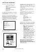
LEGEND SE MOBILE CLEANING UNIT Operating Instructions (ENG) MODELS: LEGEND SE WITH AUTO HEAT DIVERTER Read instructions before operating the machine.
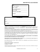
MACHINE DATA LOG/OVERVIEW MODEL _______________________________________ DATE OF PURCHASE __________________________ SERIAL NUMBER ______________________________ SALES REPRESENTATIVE # _____________________ DEALER NAME ________________________________ OPERATIONS GUIDE NUMBER ___________________ PUBLISHED ____________________________________ YOUR DEALER Name: ____________________________________________________________________________________________ Address: _________________________________________________
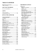
TABLE OF CONTENTS Machine Data Log/Overview. .........................1 Table of Contents ...........................................2 HOW TO USE THIS MANUAL How to use this Manual..................................1-1 SAFETY Safety Instructions .........................................2-1 Hazard Intensity Level ...................................2-3 INSTALLATION & OPERATION Technical Specifications................................3-1 Receiving Your Unit .......................................
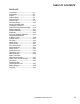
TABLE OF CONTENTS PARTS LIST Front Panel.........................................5-1 Framework .........................................5-3 Engine ................................................5-5 Engine Starter ....................................5-7 Vacuum Pump ...................................5-9 Water Pump.......................................5-11 Chemical Pump..................................5-15 Vacuum Exhaust Heat Exchanger & Silencer ........................5-17 Engine Exhaust Heat Exchanger..
HOW TO USE THIS MANUAL This manual contains the following sections: - - HOW TO USE THIS MANUAL SAFETY INSTALLATION REQUIREMENTS INSTALLATION OPERATIONS MAINTENANCE & SERVICE PARTS LIST The HOW TO USE THIS MANUAL section will tell you how to find important information for ordering correct repair parts. Parts may be ordered from authorized dealers. When placing an order for parts, the machine model and machine serial number are important.
IMPORTANT SAFETY INSTRUCTIONS When using this machine, basic precaution must always be followed, including the following: READ ALL INSTRUCTIONS BEFORE USING THIS MACHINE. These symbols mean WARNING or CAUTION. Failure to follow warnings and cautions could result in fatality, personal injury to yourself and/or others, or property damage. Follow these instructions carefully! Read the operator's manual before installing or starting this unit.
DO NOT leave the vehicle engine running while operating this unit. Dangerous Acid, Explosive Gases! Batteries contain sulfuric acid. To prevent acid burns, avoid contact with skin, eyes and clothing. Batteries produce explosive hydrogen gas while being charged. To prevent a fire or explosion, charge batteries only in well ventilated areas. Keep sparks, open flames, and other sources of ignition away from the battery at all times. Keep batteries out of the reach of children.
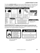
HAZARD INTENSITY LEVEL The following WARNING LABELS are found on your LEGEND SE console. These labels point out important Warnings and Cautions which should be followed at all times. Failure to follow warnings and cautions could result in fatality, personal injury to yourself and/or others, or property damage. Follow these instructions carefully! DO NOT remove these labels. Order Part #48-941212 to get a complete set of decals (safety and instrumentation) for your LEGEND SE cleaning unit.
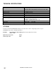
TECHNICAL SPECIFICATIONS ITEM Engine speed Water pump rpm Vacuum pump rpm Water flow rate Water pump pressure Vacuum relief valve Waste tank capacity Console weight Console weight (with waste tank & accessories) TORQUE VALUES Engine hub Vacuum pump hub DIMENSION/CAPACITY 2600 rpm (high speed in H.E. position) 1400 rpm (idle speed in Muffler position waster pump OFF. 1395 rpm 3195 rpm 3.5 GPM (maximum) 1000 PSI (maximum) 13” Hg (13” Legend Hg - SE) 70 gallons (60 gallons to shut-off) 640 lbs. (730 lbs.
RECEIVING YOUR UNIT 10. Waste tank filter and strainer basket. DEALER RESPONSIBILITY The PROCHEM dealer from whom you purchased this mobile cleaning unit is responsible for the correct installation of this machine. The dealer is also responsible for initial training of your operators and maintenance personnel in the proper operation and maintenance of this unit. 11. 100 ft. of 2” vacuum hose. 12. 1 vacuum hose connector. 13. 100 ft. of 1/4" high pressure hose with quick connects. 14. 50 ft.
INSTALLATION FUEL REQUIREMENTS Prior to starting the installation, first read the ENTIRE "Installation” section of this manual. Since the LEGEND SE cleaning unit (with waste tank and accessories) weighs approximately 886 pounds (976 lbs. if mounted on water tank), consider the following recommendations before installing this unit. 1. The unit should NOT be mounted in any motor vehicle of less than 1/2 ton capacity, or 3/4 ton if equipped with one or more auxiliary fresh water tanks.
INSTALLATION CHEMICAL REQUIREMENTS The Prochem LEGEND SE, due to its chemical injection pump design, can be used with a variety of water-diluted chemical compounds (either acidic or alkaline), depending on the job to be done. However, to obtain optimum results with this unit, we recommend using the Prochem line of chemicals. For information on using the cleaning compounds, refer to the Prochem chemical manual.
INSTALLATION BOLTING DOWN THE UNIT AND WASTE TANK All units must be bolted to the floor of the vehicle by a PROCHEM DISTRIBUTOR. LIFTING THE UNIT ONTO THE VEHICLE Since the Prochem LEGEND SE console weighs approximately 640 lbs. (730 lbs. if mounted on water tank), we recommend using a fork lift to lift the unit onto the vehicle. Position the forks under the unit from the front and make CERTAIN that the forks are spread to the width of the base.
INSTALLATION LEGEND SE 980059 07/23/02 3-6
INSTALLATION BATTERY CONNECTION WASTE TANK TO CONSOLE CONNECTION NOTE: Before connecting any hoses to the waste tanks, make certain the hose clamps are on each hose. 1. See Figure 11. Connect the 12” long section of 2” I.D. internal vac hose to the 2” dia. vac inlet tube on the console and the 2” dia. inlet tube on the waste tank. Tighten the hose clamps. 2. Connect the 25” long section of 2-7/8" I.D. internal vac hose to the 2-7/8” dia.
INSTALLATION FIGURE 11 SPECIAL INSTRUCTIONS: 1. Cut hoses to fit, if necessary. 3. 2. When cutting hoses, make certain that the cutting blade is facing away from you hands, fingers, or any other part of your body to avoid injury. Do not install hoses with excessive bends or kinks. 4. Place clamps on hoses before installing. 5. Tighten all hose clamps firmly.
INSTALLATION AUXILIARY WATER TANK CONNECTION Your cleaning unit may be equipped with an auxiliary water tank mounted underneath the console. If so, you will need to install the demand pump assembly. (See “Illustrated Parts Listings” for demand pump dimensions.) The demand pump should be situated in a location where it is easily accessible. We have provided hoses which are long enough to reach their connections on the console and auxiliary water tank.
INSTALLATION The decals should be placed in a prominent spot on the vehicle where access is given to operate the unit. The illustrations above suggest the location and placement of the decals. When placing the decals, be sure the area is clean of any dirt and possible wax build-up. Place the decal by starting at on edge and smoothing he decal over to the other edge. This will help eliminate air bubbles and allow the decal to adhere better. After a time the decals may become damaged or worn.
OPERATION This chapter of the operator’s manual divides the unit up into systems and explains how each system works. Before proceeding into the operation and maintenance sections of this manual, we recommend acquiring a basic knowledge of how this unit functions. Read the next section of this manual carefully and completely. WATER PUMPING SYSTEM See Figures 14 and 15. Cold water enters the console through the water inlet connection located on the lower front panel.
OPERATION HEAT TRANSFER SYSTEM See Figures 14 and 15. Water is heated through a two stage heat exchange system which uses vacuum pump exhaust and engine exhaust. Stage one utilizes vacuum exhaust heat blowing over a radiator-type heat exchanger prior to discharging the exhaust into the atmosphere. When the tool valve is closed, the water bypasses from the pressure regulator manifold back to the water box through the vacuum exhaust heat exchanger. The water is heated as it flows through this heat exchanger.
OPERATION FIGURE 14 3-13 LEGEND SE 980059 06/19/03
OPERATION FIGURE 15 LEGEND SE 980059 06/19/03 3-14
OPERATION VACUUM SYSTEM An exhaust diverter valve is located on the engine exhaust system. This directs the exhaust either to the heat exchanger for high temperature cleaning or to the exhaust muffler for low temperature cleaning or extraction, such as for flood restoration. When the diverter valve is in the MUFFLER position, a relay automatically shuts off the water pump. An override switch on the control panel will enable you to turn the water pump ON, for low temperature cleaning. . See Figure 16.
OPERATION CHEMICAL PUMPING SYSTEM See Figure 17. The chemical is drawn from the chemical container through a strainer into the flow meter. The flow meter indicates the rate of chemical flow. The chemical then flows through a metering valve to the solution outlet. This valve controls the rate of flow of chemical injection into the cleaning solution, which is indicated on the flow meter. The chemical then flows through a check valve into a pulse-powered chemical pump.
OPERATION FILLING AUXILIARY WATER TANK Operate this unit and equipment only in a wellventilated area. Exhaust fumes contain carbon monoxide which is an odorless and deadly poison that can cause severe injury or fatality. DO NOT operate this unit where the exhaust may enter any building doorway, window, vent, or opening of any type. 1. Your cleaning unit may be equipped with an auxiliary water tank mounted underneath the console.
OPERATION FIGURE 18 EXHAUST DIVERTER SOLENOID ROTARY LEGEND SE 980059 06/19/03 3-18
OPERATION HIGH PRESSURE HOSE Before starting the unit, connect the pressure hose to the solution outlet connection at the front of the unit. Connect the cleaning tool to the pressure hose . 3. The heat bypass valve allows you to decrease the solution temperature manually. Opening the valve (counter-clockwise) decreases the temperature by allowing hot water to bypass to the waste tank. DANGER WATER UNDER HIGH PRESSURE AT HIGH TEMPERATURE CAN CAUSE BURNS, SEVERE PERSONAL INJURY, OR COULD BE FATAL.
OPERATION 2. PRIMING THE CHEMICAL PUMP NOTE: Prochem recommends that the chemical pump be primed whenever the water pump is ON. This will eliminate possible pressure fluctuations and water pump pulsation’s related to a dry chemical pump. 1. Place the chemical inlet tube and the chemical prime tube into the chemical container.
OPERATION CLEANING UPHOLSTERY CLEANING Observe the following guidelines, while cleaning: Upholstery Tool, Part #78513 1. 1. Set temperature as desired and slow down engine speed to minimize excess heat. 2. Slow engine speed down to minimize excess heat. 3. Use one (1) "80015" spray tip in the tool. 4. Pressure adjustment below 300 PSI should be made at the tool itself, by using the adjusting knob located on the valve. Before proceeding make sure the nozzles are functioning properly.
OPERATION FLOOD RESTORATION 9. Set the temperature control on the control panel to 50°. SHUTDOWN AND DAILY MAINTENANCE 1. 2. Run fresh water through the chemical injection system to flush out chemicals. We recommend removing as much moisture from your vacuum hoses as is reasonable. This will prevent spillage of solution in your vehicle when replacing hoses. 3. Position the throttle control to about 3/4 of the way out, but no less than 1/2 of the way out. 4.
OPERATION FREEZING PROTECTION 7. If the unit is exposed to freezing weather the water in the unit may freeze, causing SERIOUS DAMAGE to the unit. To avoid this, the following is recommended during the cold weather season: Turn the water pump switch OFF. Attach the winterizing loop hose with attachment, Part #10-805380, to the solution outlet connection and the water inlet connection. Turn the water pump switch ON.
OPERATION 7. REMOVING ANTI–FREEZE FROM THE UNIT 1. Connect one end of the winterizing loop hose to the solution outlet connection. Place the other end of the loop hose, without the attachment, into an approved container. 2. Start the unit. Allow the anti-freeze to flow into the container until flow stops. 3. Fill the water box with fresh water and repeat step #2. 4. Connect the water inlet hose to the water inlet connection on the console. Turn the water supply on. 5.
MAINTENANCE SERVICE SCHEDULE Engine Vacuum Pump Water Pump Vacuum Inlet Filter (In Waste Tank) Vacuum Hoses Automatic Waste Pump Vacuum pump Engine Engine Water pump inlet filter (In water box) Battery Bypass manifold orifice & strainer Solution outlet Y-Strainer High pressure hoses Engine Pressure regulator Engine Engine Battery Engine Engine Engine Heat bypass and chemical valves Engine Temperature solenoid Vacuum exhaust heat exchanger Water pump Vacuum pump Pulley set screws & hub cap screws Drive pulle
MAINTENANCE RECOMMENDED SAE VISCOSITY GRADE WARNING DANGER WARNING 10W-30 5W-20, 5W-30 E LE CTRICAL S HOC K COUL D CAUS E SE V ERE BURNS OR INJURY . DO NO T T OUCH E LE CTRICAL W IRE S O R WAT ER UNDE R HI G H P RE SS URE AT CO MPO NE NTS W HIL E THE HI GH TE M PE RATURE CAN CAUS E BURNS , S E VE RE P E RS ONAL E NG INE IS RUNNING . I NJURY, OR COULD BE F ATAL .
MAINTENANCE VACUUM PUMP Refer to the Vacuum Pump Operation and Service Manual for specific instructions. Lubrication: We recommend that you use AEON PD Synthetic Blower Lubricant in the gear end of the vacuum pump for all operating temperatures. AEON PD is formulated especially for positive displacement blower service to provide maximum blower protection at any temperature. One filling of AEON PD will last a minimum of 2 times longer than a premium mineral oil.
MAINTENANCE WATER PUMP DRIVE BELTS, PULLEYS, & HUBS Refer to the Water Pump Operation and Service Manual for specific instructions. 1. Check pulley set screws and/or hub cap screws after the first 25 hours and then again at 100 hours. Re-torque these screws with a torque wrench, using the values on the chart on the next page. Check pulley set screws and/or hub cap screws every 500 hours thereafter. 1. Check the crankcase oil level daily to assure the proper level.
MAINTENANCE FLOAT VALVE (WATER BOX) CHECK VALVE (OUTLET) Check the float valve at least once a month for proper operation. If overfilling is a problem, check the plunger for a proper seat. Replace tip on plunger if needed or damaged. Water level in the water box should be about 5-1/2" to 6”. Inspect the check valve when rebuilding the chemical pump or as needed. Remove and disassemble the check valve. Check the Teflon seat for debris or abnormal wear. Clean or replace seat if needed.
MAINTENANCE 1. PRESSURE REGULATOR Lubricate the o-rings every 100 hours. Use o-ring lubricant Part #05-008035. Check the fluid level in the battery every 25 hours or once a week. If low, fill to the recommended level with distilled water ONLY. For the procedure, see the "General Service Adjustments” section in this manual for details. NOTE: DO NOT overfill the battery. Poor performance or early failure due to loss of electrolyte will result. VACUUM HOSES 2.
MAINTENANCE VACUUM EXHAUST HEAT EXCHANGER OPTIONAL WASTE PUMP-OUT 1. At the end of each work day, make certain that you remove any debris or sediment which may be inside the waste pump. Remove the waste pump unit from the waste tank and clean inside the screen at least once a week, or more frequently if required. 2. Cleaning the vacuum exhaust pre-heater core is recommended as needed or if the unit was operated with the vacuum inlet filter damaged, removed, or improperly installed.
MAINTENANCE GENERAL SERVICE ADJUSTMENTS DO NOT service this unit while it is running. The high-speed mechanical parts as well as high temperature components may result in severe injury, severed limbs, or fatality. ENGINE SPEED 2. 4. After adjusting, re-tighten the four nuts which hold the vacuum pump mount in position. Check belt alignment with straight- edge. 5. Readjust and check air pump belt. DO NOT over-tighten belt. Re-tighten the two nuts which hold the air pump mount in place.
MAINTENANCE BYPASS MANIFOLD CHECK VALVE (SOLUTION OUTLET) Clean the bypass strainer and orifice using the following guidelines: Inspect the check valve whenever doing service on the chemical pump or if flow problems occur in the chemical system: 1. 2. Remove the strainer. Clean and re-install. DO NOT over-tighten strainer. Remove the cap. Remove the orifice, using a 3/16" Allen wrench (the 3/16" Allen wrench is provided with Part #66-945280, the bypass maintenance kit.) BYPASS MANIFOLD DETAIL 1.
MAINTENANCE CHEMICAL PUMP PRESSURE REGULATOR The only repairs which the chemical pump may require is the replacement of the diaphragm or check valves. To replace the diaphragm, unscrew the cover from the body. When replacing the diaphragm, lubricate the outer edges of the diaphragm with o-ring lubricant, Part #05-008035, and reassemble. To replace the check valves, unscrew the check valve caps. Replace the check valves and reassemble, using new o-rings.
MAINTENANCE TEMPERATURE SOLENOID The temperature solenoid may become seized due to hard water deposits. Make certain that the core moves freely in the stem. Also, the plunger must move freely within the guide. Clean with #0000 steel wool. Check the seat to make sure that it is not distorted. Clean the seat, using a 3/64” drill bit. ROTATE THE DRILL BIT WITH YOUR FINGERS ONLY. NOTE: DO NOT over-tighten nut when reassembling temperature solenoid. Overtightening the nut will damage the coil.
MAINTENANCE TEMPERATURE CAPILLARY & PACKING ASSEMBLY INSTALLATION INSTRUCTIONS 1. Using thread sealant, thread the tapered end of the union fitting into the thermostat manifold and tighten. 2. Slide the jam nut over the capillary bulb with the threaded end toward the end of the capillary bulb. 3. Insert the capillary bulb through the union fitting and into the thermostat manifold. 4. Place the rubber seal onto the capillary tube with the split facing 90° from the top (see the capillary union detail).
TROUBLESHOOTING PROBLEM Loss of water pump pressure. With the cleaning tool open, the water pressure gauge reads below the normal operating pressure. NOTE: If the water pump pressure drops below 50 PSI or exceeds 1200 PSI, the unit will automatically shut down. CAUSE SOLUTION Water supply is turned off or the float Turn the water supply on or up. Check valve is stuck or improperly adjusted. for kinks in the water supply hose.
TROUBLESHOOTING PROBLEM Loss of vacuum While cleaning, the vacuum is not up to par. Engine RPM is normal. Loss of chemical With the cleaning tool valve open, no chemical Chemical flow meter indicates flow with the tool valve closed CAUSE SOLUTION Examine the tubing between the vauum Vacuum gauge is giving an improper relief valve and the vacuum gauge and reading. remove any blockage. Vacuum hose(s) is damaged, Inspect all lines, remove accumulated causing a suction leak.
TROUBLESHOOTING PROBLEM Water pump does not engage when the diverter valve is in the “Heat Exchanger” position Engine will not start The engine does not turn over CAUSE SOLUTION If the blue light is OFF, check the water Water pump circuit breaker has pump circuit breaker on the control panel. been tripped Press the ciruit breaker reset button. If the blue light is OFF and the water pump circuit breaker is not tripped, examine Defective electrical connection in switch, electrical connections, and wiring.
TROUBLESHOOTING PROBLEM Starter turns over engine, but will not start CAUSE Defective 285°F high temperature shutdown switch (located at rear of exhaust heat exchanger). Engine is malfunctioning Engine is out of gasoline Waste tank is full Water pressure has dropped below 50 PSI, triggering the the pressure switch to shut the unit down. Water pressure has exceeded 1200 PSI, triggering the pressure switch to shut the unit down. Main circuit breaker on the control panel has been tripped.
TROUBLESHOOTING PROBLEM Heat exchanger leaks NOTE: The engine exhaust heat exchanger will produce water condensation discharge at times during normal operation. DO NOT confuse this with a leak. Loss of temperature CAUSE SOLUTION Engine and vacuum exhaust heat exchanger are damaged from frozen water Check instrumentation settings: Diverter valve is in the MUFFLER position. Temperature bypass valve is open. Temperature control is set at a low temperature. Defective solenoid - remains in open position.
THIS PAGE LEFT BLANK INTENTIONALLY LEGEND SE 980059 07/23/02 4-18
FRONT PANEL 39 1 2 3 4 5 6,7 7,8 9 10 37,38 11 36 34,35 9 33 12 13,14 32 15-18 30,31 29 19 28 20 27 21 22 25,26 24,24A 5-1 23 LEGEND SE 980059 07/01/02
FRONT PANEL SERIAL NO. FROM REF PART NO.
FRAMEWORK 8 17 18 19 16 15 14 20 21 8 1 2 1 22 7 9 13 6 5 2 1 12 1 11 10 1 2 3 2 3 27 27 4 3 2 1 1 1 26 24 2 2 28 25 1 22 2 23 19 5-3 LEGEND SE 980059 07/23/02 2 22
FRAMEWORK SERIAL NO. FROM REF PART NO. DESCRIPTION 1 2 3 4 5 6 7 8 9 10 11 12 13 14 15 16 17 18 19 20 21 22 23 24 25 26 27 28 02-000066 87162 70270 56-501992 70075 56-502025 56-502026 00-000216 50-501768 87144 87176 00-000222 54-501653 56-501993 42-902282 87139 87165 70497 57006 56-501929 58-700024 00-000286 00-000210 790074 790070 56-501857 70105 56-502050 FLATWASHER, 1/4 WASHER, 1/4 SPLIT LOCK SCR, 1/4-20 X 3/4 HHCS PLTD GUARD, BELT SCR, 1/4-20 X 4.
ENGINE 2 1 29 28 27 24 26 3 25 4 FROM BULHEAD ADAPTER ON VEHICLE FLOOR 5 23 6 20 7 22 21 10 15 8 11 14 17 18 19 5-5 16 12 TO EXHAUST DIVERTER VALVE ASSEMBLY LEGEND SE 980059 07/23/02 13 9
ENGINE SERIAL NO. FROM REF PART NO.
ENGINE STARTER 3 1 2 4 TO BATTERY NEGATIVE (-) TERMINAL 5 6 5 9 7 8 TO BATTERY POSITIVE (+) TERMINAL 5-7 LEGEND SE 980059 07/23/02
ENGINE STARTER SERIAL NO. FROM REF PART NO. DESCRIPTION 1 2 3 4 5 6 7 8 9 42-902292 64-950514 42-902290 57031 87083 02-000143 70601 64-950515 70262 KOH SOLENOID #5243502 CABLE, BAT X 101” RED KOH STARTER #1209803 NUT, 5/16-18 HEX WASHER, 5/16 SPLIT LOCK PLTD FLATWASHER, 5/16 SCR, 5/16-18 X 2.
VACUUM PUMP 16 10 29 25 3 28 26 VENT CAP 1 TO VACUUM MUFFLER 2 27 4 6 5 FROM WASTE TANK 7 24 8 3 9 12 30 11 10 23 13 14 22 21 17 15 20 19 12 18 16 5-9 LEGEND SE 980059 07/23/02
VACUUM PUMP SERIAL NO. FROM REF PART NO. DESCRIPTION 1 2 3 4 5 6 7 8 9 10 11 12 13 14 15 16 17 18 19 20 21 22 23 24 25 26 27 28 29 - 41-905021 54-501593 03-000112 09-805396 54-501735 44-802237 44-802218 44-802204 00-000340 87171 87163 70266 12-800101 18-808525 19-800075 12-800059 09-805224 09-805440 02-000057 00-000323 70357 56-502324 61-950451 09-805341 57114 04-000091 52-501573 56-501615 43-807074 05-008039 05-008032 PUMP, VAC 4M-L NIP, VAC EXH OUTL CLAMP, HOSE #48 HOSE, INT VAC 2.88 X 2.
WATER PUMP 2 1 10 TO PRESSURE MANIFOLD 9 3 8 34 11 33 32 11 12 13 14 7 26 6 31 FROM WATER BOX 5 30 29 28 4 25 12 13 27 FROM TOP OF FLOW METER 19 20 24 15 TO CHEMICAL ON/OFF PRIME VALVE 23 16 5 22 7 21 5-11 15 18 LEGEND SE 980059 09/10/02 17
WATER PUMP SERIAL NO. FROM REF PART NO.
WATER PUMP 1 4 3 2 7 5 6 16 15 13 12 7 14 17 11 17 10 8 9 18 5-13 LEGEND SE 980059 07/23/02
WATER PUMP SERIAL NO. FROM REF PART NO.
CHEMICAL SYSTEM 17 23 18 19 22 21 19 18 20 1 17 4 6 5 FROM WATER PUMP 9 14 2 5 4 12 6 11 24 3 4 8 10 13 9 16 4 TO SOLUTION OUTLET 8 5 5 4 15 TO CHEMICAL RESERVOIR 5-15 LEGEND SE 980059 07/23/02 7
CHEMICAL SYSTEM SERIAL NO. FROM REF PART NO.
VACUUM EXHAUST HEAT EXCHANGER AND SILENCER 6 5 3 4 2 1 FROM VACUUM PUMP 9 7 10 6 5 4 7 FROM DIVERTER VALVE 8 11 19 FROM PRESSURE REGULATOR MANIFOLD 16 12 18 5 4 13 6 14 17 16 5-17 TO WATER BOX 15 LEGEND SE 980059 07/23/02 5 4
VACUUM EXHAUST HEAT EXCHANGER AND SILENCER SERIAL NO. FROM 1 PART NO. DESCRIPTION 1 2 3 4 5 6 7 8 9 10 11 12 13 14 15 16 17 18 19 56-501928 03-000081 57-520099 02-000066 87162 70270 03-000112 09-805344 56-501892 57-520082 09-805396 00-000078 43-807080 58-700027 09-805368 03-000246 61-950696 09-805384 43-807081 EXH OUTLET CLAMP, MFLR 1-1/2 ZNC PL MUFFLER, ENG EXH VERSION D (FLNG) FLATWASHER, 1/4 WASHER, 1/4 SPLIT LOCK SCR, 1/4-20 X 3/4 HHCS PLTD CLAMP, HOSE #48 HOSE, INT VAC 2.88 X 3.
ENGINE EXHAUST HEAT EXCHANGER 6 22 21 20 5 FROM HELI-COIL HEAT EXCHANGER FROM DIVERTER VALVE 18 19 4 7 16 17 8 3 2 TO SOLUTION OUTLET 22 21 15 20 14 1 13 11 12 5-19 LEGEND SE 980059 07/23/02
ENGINE EXHAUST HEAT EXCHANGER SERIAL NO. FROM REF PART NO.
BYPASS MANIFOLD FROM Y-STRAINER/CHECK VALVE MANIFOLD 6 12 1 11 2 10 3 TO TEMPERATURE SOLENOID 4 9 4 8 5 6 7 TO WATER BOX 13 17 14 16 5-21 15 LEGEND SE 980059 07/23/02
BYPASS MANIFOLD SERIAL NO. FROM REF PART NO. DESCRIPTION 1 2 3 4 5 6 7 8 9 10 11 12 13 14 15 16 17 10-805357 12-500040 56-501906 12-800065 10-805130 87162 00-000132 15-808112 10-805130 70105 02-000066 57006 52-501659 52-501701 43-810053 53-501523 14-806552 HOSE, 3/16 X 38 (1/4FT BS) MET ELL, 1/8P C 1/4T BR ASSY, BRKT, BYPASS MTG CONN, 1/8P X 1/4T HOSE, 3/16 X 13-1/2 (1/4FT BS) WASHER, 1/4 SPLIT LOCK SCR, 1/4-20 X 1-1/2 HXHD ASSY, BYPASS MNFLD HOSE, 3/16 X 13-1/2 (1/4FT BS) SCR, 1/4-20 X 1.
SOLUTION OUTLET 11 9 10 12 FROM CHEMICAL METERING VALVE 13 8 14 17 16 7 5 3 15 18 6 TO BYPASS 4 MANIFOLD 19 20, 21 2 23 25 22 1 24 30 31 38 27 33 26 35 32 15 13 28 15 FROM ENGINE EXHAUST HEAT EXCHANGER 5-23 34 16 16 29 LEGEND SE 980059 07/23/02 19 36 37
SOLUTION OUTLET SERIAL NO. FROM REF PART NO.
WATER BOX 34 28 33 29 30 32 31 1 6 5 26 27 4 2 3 25 23 24 23 18 17 22 16 7 21 8 9 21 19 15 10 14 14 SEE WATER PUMP 11 12 13 5-25 LEGEND SE 980059 07/23/02
WATER BOX SERIAL NO. FROM REF PART NO.
PRESSURE REGULATOR MANIFOLD TO PRESSURE GAUGE 1 4 5 7 6 3 2 7 19 8 11 10 17 16 12 15 TO EXHAUST HEAT EXCHANGER 14 9 13 FROM WATER PUMP TO VACUUM EXHAUST HEAT EXCHANGER 20,21 20 22 20,21 20 20,21 5-27 LEGEND SE 980059 11/07/02
PRESSURE REGULATOR MANIFOLD SERIAL NO. FROM REF PART NO. DESCRIPTION 1 2 3 4 5 6 7 8 9 10 11 12 13 14 15 16 17 18 19 20 21 790106 87162 00-000210 10-805294 12-800346 11-800275 11-800345 12-800347 10-805424 10-805275 12-800282 11-800224 09-805384 03-000246 12-800345 11-800341 790067 11-800429 790112 16-808201 16-808200 ACCUMULATOR WASHER, 1/4 SPLIT LOCK PLTD SCR, 1/4-20 X 3/4 SOCHD HOSE, 3/16 X 11.
TEMPERATURE SOLENOID & BYPASS VALVE 2 1 TO VACUUM INLET TUBE 3 4 18 5 8 9 17 FROM BYPASS MANIFOLD 16 6 15 14 11 13 7 10 12 5-29 LEGEND SE 980059 07/23/02
TEMPERATURE SOLENOID & BYPASS VALVE SERIAL NO. FROM REF PART NO.
DIVERTER VALVE 3 14 9 5 14 20 11 3 2 9 4 5 4 18 11 2 2 7 6 3 19 16 10 8 17 1 7 2 12 15 5-31 LEGEND SE 980059 07/23/02 13
DIVERTER VALVE SERIAL NO. FROM REF PART NO.
AIR PUMP 1 2 4 7 6 5 2 8 5 4 11 2 9 3 12 10 2 3 14 13 15 25 16 24 17 17 22 18 23 12 19 21 20 16 16 5-33 LEGEND SE 980059 07/23/02
AIR PUMP SERIAL NO. FROM REF PART NO.
WASTE TANK 5 6 7 1, 2 3 35 36 8, 8A 4 9 26 10 23 11 34 12 18 17 32 33 FROM WATER BOX 16 31 TO VACUUM PUMP 13 30 29 28 19 27 26 FROM VACUUM INLET TUBE 14 15 23 39 37 25 23 24 20 21 22 5-35 LEGEND SE 980059 07/23/02 40 38 36
WASTE TANK SERIAL NO. FROM REF PART NO.
WASTE PUMP 7 8 6 FROM CORD 5 9 10 BLK- 11 3 WHT+ BLK- 16 FROM PUMP 12 4 31-900200 CONN, BUTT W/HT SHRINK GRY GRY BRN+ SWITCH FROM PUMP 13 18 17 1, 2 19 21 23 14, 15 25, 46 26 27 20 28 29 22 30 31 24 22 40 41 42, 43 44 7 45 37 22 32 33 MOUNTS TO FRAME 38 39, 46 35 36 34 47 5-37 LEGEND SE 980059 07/23/02
WASTE PUMP SERIAL NO. FROM REF PART NO.
HOSE ACCESSORIES 1 2 3 2 7 4 5 10 6 11 12 9 8 14 13 17 18 19 15 21 20 16 5-39 LEGEND SE 980059 06/19/03
HOSE ACCESSORIES SERIAL NO. FROM REF PART NO.
WAND - QUAD-JET 27 28 29 30 31 32 33 34 14 9, 10 16 17 8 7 18 12 11 4 6 5 2 13 15 3 14 1 21, 22 25 26 19, 20 23, 23A, 23B 19, 24 5-41 LEGEND SE 980059 06/19/03
WAND - QUAD-JET SERIAL NO. FROM REF PART NO.
WAND - TRI-JET 25 26 27 29 30 28 31 16 14 17 9, 10 32 8 7 18 12 6 5 4 11 13 15 3 2 1 24 23 20, 21, 22 5-43 LEGEND SE 980059 06/19/03 19, 19A, 19B
WAND - TRI-JET SERIAL NO. FROM REF PART NO.
WAND - STAIR TOOL 16 17 18 20 19 21 22 2 3 23 4 6 1, 1A 5, 5A 7 8 9, 10 11 12 14 13 15, 15A 5-45 LEGEND SE 980059 06/19/03
WAND - STAIR TOOL SERIAL NO. FROM REF PART NO.
UPHOLSTERY TOOL 20 21 22 23 24 25 27 28 26 29 30 37 31 8 34 36 33 32 7 6 35 4 11 3 5 1 9 10 12 14 16 2 13 18 15 19 17 3 5-47 LEGEND SE 980059 06/19/03
UPHOLSTERY TOOL SERIAL NO. FROM REF PART NO.
SHELF ASSEMBLY 16 17 1 15 3 4 3 2 2 6 5 4 7 10 8 5 2 9 12 11 2 10 14 4 13 10 2 5 OVERALL DIMESNION: 41-1/2" TALL 50-1/8" WIDE 57" WIDE (WITH TOOL HOLDERS) 7-7/8" DEEP 10 2 12 DIMESIONAL DATA 50 1/8 7 5 1 5-49 LEGEND SE 980059 06/19/03 11
SHELF ASSEMBLY SERIAL NO. FROM REF PART NO. DESCRIPTION 1 2 3 4 5 6 7 8 9 10 11 12 13 14 15 16 17 65-950392 56-501921 02-000066 87162 70721 70270 50-501840 56-502067 56-501942 50-501753 01-000105 56-501922 50-501749 56-501920 46-802506 50-501755 50-501754 48-941152 VAN STORAGE UNIT PC SHELF, LWR FLATWASHER, 1/4 WASHER, 1/4 SPLIT LOCK SHOULDER BOLT, 182 OD X 2.
WATER TANK - DUAL WITH DEMAND PUMP 1 1 4 3 2 2 3 4 13 5 12 13 6 7 9 8 11 6 7 10 8 TO DEMAND PUMP 8 OVERALL DIMNSION: 32-1/2" TALL 62-5/8" WIDE 15-1/2" DEEP 14 5-51 LEGEND SE 980059 06/19/03
WATER TANK - DUAL WITH DEMAND PUMP SERIAL NO. FROM REF PART NO.
WATER TANK - DEMAND PUMP 3 2 4 1 11 6 5 4 10 4 9 12 12 13 4 4 8 7 5-53 8 LEGEND SE 980059 06/19/03
WATER TANK - DEMAND PUMP SERIAL NO. FROM REF PART NO. DESCRIPTION 1 2 3 4 5 6 7 8 9 10 11 12 13 70305 87083 02-000143 03-000113 09-805278 09-805357 09-805446 12-800345 13-806009 14-806553 41-905049 20381-022 11-800275 SCR, 5/16-18 X 3/4 HHCS GR5 PL TDL WASHER, 5/16 SPLIT LOCK PLTD WASHER, 5/16 FLAT CLAMP, HOSE #12 SST HOSE, WATER 3/4 X 3” HOSE, WATER .75 X 5.
HOSE REEL OVERALL 1 47" TALL 44-1/2" DEEP 21 23 22 24 25 17 13 14 15 5 6 16 8 13 14 2 7 12 16 15 15 3 9 2 5 3 13 6 10 11 12 10 14 7 9 4 5-55 LEGEND SE 980059 06/19/03 8
HOSE REEL SERIAL NO. FROM REF PART NO.
WATER BOX WITH AUXILIARY WATER TANK 26 4 25 30 18 29 14 22 11 13 3 8 23 7 31 32 15 2, 7 28 19 5 17 9 24 19 21 29 17 10 34 24 21 12 21 27 5-57 LEGEND SE 980059 06/19/03 20 6 1
WATER BOX WITH AUXILIARY WATER TANK SERIAL NO. FROM REF PART NO.
WIRING DIAGRAM 5-59 LEGEND SE 980059 06/19/03
WIRING DIAGRAM LEGEND SE 980059 06/19/03 5-60
THIS PAGE LEFT BLANK INTENTIONALLY 5-61 LEGEND SE 980059 06/19/03
LIMITED WARRANTY Prochem warrants your machine to be free of defects in material and workmanship. This warranty shall extend to the designated parts for the specific time period listed from the date of delivery to the user. If Prochem receives notice of such defects during the warranty period, Prochem will either, at its option, repair or replace products which prove to be defective. Any local or distant transportation, related service labor, normal maintenance, and diagnostic calls are not included.