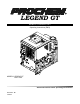
LEGEND GT MOBILE CLEANING UNIT Operating Instructions (ENG) MODELS: LEGEND GT 1.001-119.0 Read instructions before operating the machine.
Left intentionally blank
Machine Data Label Model: Date of Purchase: Serial Number: Dealer: Address: Phone Number: Sales Representative: Overview Welcome…and congratulations on the purchase of your Mobile Cleaning Unit. This instruction manual is a guide for operating and servicing your unit. Read this manual completely before installing or operating this unit. This unit offers you personal convenience. All of your instrumentation and controls have been positioned to give you easy access for operation and daily maintenance.
Table of Contents Overview . . . . . . . . . . . . . . . . . . . . . . . . . . . . . . . . . 1 Machine Data Label . . . . . . . . . . . . . . . . . . . . . . . . . 1 Table of Contents . . . . . . . . . . . . . . . . . . . . . . . . . . . 2 Receiving Your Unit . . . . . . . . . . . . . . . . . . . . . . . . . 4 Acceptance of Shipment . . . . . . . . . . . . . . . . . . . . . 4 Equipment List . . . . . . . . . . . . . . . . . . . . . . . . . . . . . 4 How to Use This Manual . . . . . . . . . . . . . . . . . .
Table of Contents Maintenance Parts Service Schedule . . . . . . . . . . . . . . . . . . . . . . . . . . 36 Key Checkpoints . . . . . . . . . . . . . . . . . . . . . . . . . . . 38 External Fuel Pump Maintenance. . . . . . . . . . . . . . 38 Chemical Supply System Maintenance . . . . . . . . . 38 Heat Exchanger System Maintenance . . . . . . . . . . 38 Vacuum Pump Maintenance. . . . . . . . . . . . . . . . . . 39 Engine. . . . . . . . . . . . . . . . . . . . . . . . . . . . . . . . . . . 39 Vacuum Pump .
Receiving Your Unit Acceptance of Shipment Equipment List Every part of your cleaning unit was carefully checked, tested, and inspected before it left our manufacturing plant. Upon receiving the unit, make the following acceptance check: 1. Console. 1. The unit should not show any outward signs of damage. If damaged, notify the common carrier immediately. 4. 100 ft. of 2” vacuum hose. 2. Check your equipment and packing list.
How to Use This Manual This manual contains the following sections: • • • • • • How to Use This Manual Safety Installation Operations Maintenance & Service Parts List The INSTALLATION section contains information on how to properly install the unit in your vehicle. The OPERATIONS section is to familiarize the operator with the operation and function of the machine. The HOW TO USE THIS MANUAL section will tell you how to find important information for ordering correct repair parts.
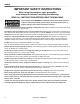
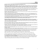
Safety IMPORTANT SAFETY INSTRUCTIONS When using this machine, basic precaution must always be followed, including the following: READ ALL INSTRUCTIONS BEFORE USING THIS MACHINE. These symbols mean WARNING or CAUTION. Failure to follow warnings and cautions could result in fatality, personal injury to yourself and/or others, or property damage. Follow these instructions carefully! Read the operator's manual before installing or starting this unit.
Safety DO NOT leave the vehicle engine running while operating this unit. Dangerous Acid, Explosive Gases! Batteries contain sulfuric acid. To prevent acid burns, avoid contact with skin, eyes and clothing. Batteries produce explosive hydrogen gas while being charged. To prevent a fire or explosion, charge batteries only in well ventilated areas. Keep sparks, open flames, and other sources of ignition away from the battery at all times. Keep batteries out of the reach of children.
Safety The following symbols are used throughout this guide as indicated in their descriptions: Hazard Intensity Level There are three levels of hazard intensity identified by signal words - WARNING and CAUTION and FOR SAFETY. The level of hazard intensity is determined by the following definitions: WARNING - Hazards or unsafe practices which COULD result in severe personal injury or death. CAUTION - Hazards or unsafe practices which could result in minor personal injury or product or property damage.
Safety Safety Labels The following WARNING LABELS are found on your cleaning unit. These labels point out important Warnings and Cautions which should be followed at all times. Failure to follow warnings and cautions could result in fatality, personal injury to yourself and/or others, or property damage. Follow these instructions carefully! DO NOT remove these labels. NOTE: If at any time the labels become illegible, promptly replace them.
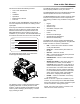
Installation Dealer Responsibility Lifting Unit Onto Vehicle Your distributor from whom you purchased this mobile cleaning unit is responsible for correct installation of this machine. The dealer is also responsible for initial training of your operators and maintenance personnel in proper operation and maintenance of this unit. Since console weighs approximately 600 lbs. pounds, (690 lbs. if mounted on water tank) we recommend using a forklift to lift unit onto vehicle.
Installation Bolting Down Unit And Waste Tank NOTE: When positioning waste tank with respect to console, hook up the vacuum hose to waste tank. This will ensure that waste tank is positioned correctly. Proceed once unit and waste tank are positioned in vehicle in desired location. Electrical Wiring Ensure all electrical wiring and battery cables are free from contact with any metal edge. Engine vibration could cause metal edge to cut wiring and possibly result in a fire.
Installation Layout with 60 Gallon Waste Tank 1" 378 1 2" 3" 2X 128 3" 1" 2X 616 2X 12 1" 74 1" 72 6X Ø13 32" 3" 1532 1" 592 6X Ø7/16" X 5/8" SLOT 1" 392 2X 24" 2X 12" 3" 2X 232 TOP VIEW 11 16" 223 8" ENSURE THAT VAC INLETS ON CONSOLE AND WASTE TANK ARE ALIGNED 3" 398 WASTE TANK 7" 338 CONSOLE 31" CONSOLE 3132 1" WASTE TANK 388 FRONT VIEW 12 86313050 LEGEND GT
Installation Layout with 60 Gallon Waste Tank & Optional Auxiliary Water Tank 3881" 3781" 1 2" 11 2X 116 " 3 2X 616 " 6X Ø13 32" 9 416 " 2X 1238" 7 232 " WASTE TANK 21 732 " 378" 21 732 " MIN.
Installation Layout with 100 Gallon Waste Tank 11 2X 116 " 4981" 1 2" 3 2X 616 " WASTE TANK 6X Ø13 32" 2X 1238" 721" 3 1532 " 31 432 " 5921" LENGTH 2X 6" 1941" 2X 12" 2X 24" 9X Ø7/16" X 5/8" SLOT CONSOLE TOP VIEW 11 16" 2238" ENSURE THAT VAC INLETS ON CONSOLE AND WASTE TANK ARE ALIGNED 3838" WASTE TANK 3338" CONSOLE HEIGHT FRONT VIEW 5081" 14 31 3132 " 86313050 LEGEND GT
Installation Layout with 100 Gallon Waste Tank & Optional Auxiliary Water Tank 5081" 4981" 1 2" 11 2X 116 " 3 2X 616 " 6X Ø13 32" 7 232 " 9 1616 " 2X 1238" WASTE TANK 21 732 " 31 332 " MIN.
Installation Waste Tank To Console Connection Fuel Pump Assembly Installation NOTE: Before connecting any hoses to the waste tanks, make certain the hose clamps are on each hose. 1. Connect the section of 2-7/8" I.D. internal vac hose between the 2-7/8" dia. vac outlet tube on the waste tank and the vacuum pump relief valve on the console. It may be necessary to cut this hose to fit. Tighten the hose clamps. 2. Connect the 2" I.D. waste removal hose to the 2" dia.
Installation Van Bulkhead Installation 1. Select a location on the vehicle floor to drill the hole for the bulkhead adapter. This location should be situated in a position that eliminates the possibility of fuel line contact by either the operator(s) or accessories during the working hours or maintenance periods. Make certain that the supplied hoses will reach the location and work with the configuration you choose. 2. Drill a 5/8" (.
Installation Fuel Supply & Return Line Installation (Underneath Van) 1. Attach the 1/8 NPT x 5/16 Hosebarb 90 degree elbow to the bulkhead adapter underneath the van to be used for the fuel supply line. 2. Cut to length the 6' piece of 5/16" 50 PSI fuel hose used for the supply line from: a. Bulkhead adapter to the outlet side of the bypass fuel filter. b. Inlet side of the bypass fuel filter to the discharge side of the fuel pump. c. Inlet side of the fuel pump to the outlet side of the inline fuel filter.
Installation Battery Connection Dangerous Acid, Explosive Gases! Batteries contain sulfuric acid. To prevent acid burns, avoid contact with skin, eyes, and clothing. Batteries produce explosive hydrogen gas while being charged. To prevent a fire or explosion, charge batteries only in well-ventilated areas. Keep sparks, open flames, and other sources of ignition away from the battery at all times. Keep batteries out of the reach of children. Remove all jewelry when servicing batteries.
Installation Initial Operational Settings Engine NOTE: Due to temperature and altitude changes, the optimal settings for each truckmount must be adjusted after installation. Failure to make these adjustments may lead to poor unit performance and premature component failure. Vacuum Pump The maximum vacuum pressure obtainable at full throttle should be 13"Hg. If the unit is drawing a stronger vacuum (at full sealed suction) than 13" Hg, adjust the vacuum relief spring to 13" Hg.
Operations Technical Specifications ITEM DIMENSION/CAPACITY 2950 rpm Engine speed 1400 rpm (idle speed) Water pump rpm 1680 rpm Vacuum pump rpm 3385 rpm Water flow rate 3.5 GPM (maximum) Solution pump pressure 1200 PSI (maximum) Vacuum relief valve 13” Hg Waste tank capacity 60 gallons / 100 gallons Console weight 600 lbs. (690 lbs. If mounted on water tank) Console weight with: 810 lbs. with empty waste tank 60 gallon waste tank & accessories 1252 lbs. with full waste tank 900 lbs.
Operations Fuel Requirements Altitude Requirements Use unleaded gasoline ONLY. DO NOT use any gasoline additives. We recommend the use of clean, fresh, unleaded gasoline intended for automotive use. High octane gasoline should NOT be used with the engine on this unit. These engines are NOT designed to use E-85 or Flex Fuels. Engines perform differently with increases/decreases in altitude. Be sure to check engine speeds during initial installation. See engine speeds in Technical Specifications section.
Operations Water Requirements Hard water deposits will adversely affect the plumbing and heat exchange systems on this unit. The map below will give you an idea of where areas of high water hardness may occur. However, any water supply obtained from a well is almost always hard water and a water softener will be needed to protect your equipment. NOTE: Equipment malfunction or component failure caused by hard water scaling is NOT covered under the warranty.
Operations Components 1 2 3 23 4 5 6 22 7 8 9 21 10 11 12 13 14 20 19 15 16 24 18 17 86313050 LEGEND GT
Operations Components 8. THROTTLE 1. VACUUM GAUGE This gauge indicates in inches of mercury how much vacuum the system is producing at any given time. 2. SOLUTION PRESSURE GAUGE This gauge registers the amount of pressure in the system. 3. WASTE PUMPOUT This switch actuates the optional waste pumpout. 4. SOLUTION TEMP GAUGE This gauge measures the temperature of the cleaning solution exiting the machine. The throttle is used to set the speed of the engine (rpm).
Operations 14. SOLUTION TEMPERATURE CONTROL VALVE This valve allows the operator to control the solution temperature by bypassing hot water to the waste tank, for low temperature cleaning such as upholstery. Turning the valve counter clockwise opens the valve. Turning clockwise closes the valve and has the effect of stopping water from bypassing. 15. CHEMICAL CHECK VALVE The chemical check valve allows chemicals to enter the system and travel in a singular direction to the wand.
Operations Vacuum System The engine turning the vacuum pump generates vacuum. The air is channeled in one side of the vacuum pump, compressed and discharged on the opposite side, creating airflow. The movement of air is used to do the work necessary for the extraction process. A vacuum nozzle applied to the carpet surface removes moisture, dirt and spent chemicals. These elements are conveyed back to a separating tank utilizing hoses and the force of air.
Operations Heat Exchanger Always wear hearing protection and proper personal protection equipment when operating unit. Water Pumping and Heat Transfer System Cold water enters the console through the water inlet. When the water box is full the valve will automatically shut off. Water then flows from the water box, through the strainer, into the solution pump. The water is pumped to the pressure regulator manifold, which provides and maintains the desired pressure setting.
Operations KOHLER ENGINE = COLD WATER = WARM WATER = HOT WATER = HOT EXHAUST AIR REAR HOT AIR FROM VACUUM PUMP HEAT EXCHANGER CORES FRONT WATER BOX WATER INLET TEMPERATURE RELIEF VALVE SOLUTION PUMP WASTE TANK PRESSURE GAUGE TEMPERATURE CONTROL VALVE CHEMICAL INJECTION CHECK VALVE SOLUTION SCREEN PULSE HOSE PRESSURE REGULATOR TEMPERATURE BALANCE ORIFICE SOLUTION OUTLET 86313050 LEGEND GT 29
Operations Chemical Injection System The chemical injection system is unique in that it utilizes the pressure spikes generated by the high pressure solution pump to move chemical into the main solution stream. The high pressure spikes move the diaphragm in the chemical pulse pump forcing small amounts of liquid chemical to be moved in a single direction of flow with the aid of two check valves. The chemical is drawn from the container, and through the flow meter, which indicates rate of flow.
Operations Pre-Run Inspection / Setup High Pressure Solution Hose NOTE: Operation of this unit is simple. However, only trained personnel should proceed. Before starting the unit, connect the high pressure solution hose to the outlet connection at the front of the unit. Connect the cleaning tool to the pressure hose. Operate this unit and equipment only in a wellventilated area. Exhaust fumes contain carbon monoxide, which is an odorless and deadly poison that can cause severe injury or fatality.
Operations Priming the Chemical Pump 1. Fill chemical container and inspect chemical strainer. Always dispose of waste in accordance with Local, State, and Federal laws. 2. Insert chemical inlet and prime tubing into chemical container. 3. Pull out engine choke, turn solution pump switch to override and turn ignition key to start. 4. Push in engine choke after engine has started. 5. Set throttle to idle position. 6. Turn on solution pump. 7.
Operations Upholstery Cleaning Freezing Protection Upholstery tool, (See Options Section) 1. To protect fabrics, reduce solution temperature as needed by opening the solution temperature control valve on the lower front panel. Engine speed may also be reduced slightly to reduce heat and vacuum. If the unit is exposed to freezing weather the water in the unit may freeze, causing SERIOUS DAMAGE to the unit. To avoid this, the following is recommended during the cold weather season.
Operations Winterizing the Unit 1. Shut off the water supply. Disconnect the water inlet hose from the front of your console. 2. Connect all high pressure solution hoses and tools that may have water in them. 3. Start the unit and turn solution pump on. Open the tool valve until water pressure drops. 4. Turn off solution pump. Fill the water box with approximately two gallons of 100% glycol base anti-freeze. 9. Prime the chemical system with 50/50 anti-freeze/ water mix.
Operations Removing Anti-Freeze From the Unit 1. Connect the water inlet hose to the water inlet connection on the console. Turn the water supply on. 2. Start unit turn on pump. 3. Connect all solution hoses and any tools which require purging of anti-freeze to the solution outlet connection(s). 4. Open the tool valves and drain the anti-freeze into an approved container until the flow is clear and all anti-freeze is purged from the tools and hoses.
Maintenance Service Schedule Engine Vacuum Pump Solution Pump Chemical Inlet Tube Strainer Vacuum Inlet Filter (In Waste Tank) Vacuum Hoses Automatic Waste Pump Vacuum Pump Water Box Float Valve Solution Pump Inlet Strainer Temperature Balance Orifice Battery Solution Outlet Screen High Pressure Hoses Pressure Regulator Pressure Regulator Engine Battery Automatic Waste Pumpout Belts/Pulleys Water Box Float Valve Seal Engine Fuel Pump Engine Engine Chemical Valves Temperature Control Valve 36 Daily Daily D
Maintenance Vacuum pump Vacuum Exhaust Heat Exchanger Solution Pump Pulley Set Screws & Hub Cap Screws, Solution Pump Clutch Shaft Bolts Drive Pulley Drive Pulley Drive Belts Drive Belts Chemical Pump & Check Valves Vacuum Lubrication Lines 250 hrs 500 hrs 500 hrs 500 hrs 500 hrs 500 hrs 500 hrs 500 hrs 500 hrs 500 hrs Engine Engine Chemical Pump & Check Valves Check Valve (Solution Outlet) Waste Tank Shut-off Float Switch Vacuum pump Waste Tank Filters/Strainers Engine Engine 500 hrs 1000 hrs 1000 hrs
Maintenance Key Checkpoints Heat Exchanger System Maintenance NOTE: Initiation of a planned preventative maintenance program will assure that your unit has optimum performance, a long operating life, and a minimal amount of "down" time. External Fuel Pump Maintenance The power plant for the unit receives fuel from the main fuel tank of your van/truck. An external fuel pump that provides this fuel is located on the underside of the van/ truck.
Maintenance Vacuum Pump Maintenance Engine (Refer to pump manufacturer’s manual for specific maintenance instructions) (Refer to engine manufacturer’s manual for specific instructions) The total function of the unit is based around the performance of the vacuum pump. Heat transfer used to raise the temperature of the solution is gained from the air drawn by the vacuum pump and solution is removed from the carpet with the vacuum suction of the vacuum pump.
Maintenance Vacuum Pump Refer to the Vacuum Pump Operation and Service Manual for specific instructions. Lubrication: We recommend that you use Tuthill Pneulube synthetic lubricant. Tuthill Pneulube synthetic lubricant is formulated especially for Tuthill rotary positive displacement blower service to provide maximum protection for all operation temperatures NOTE: Tuthill Pneulube synthetic lubricant is the oil which PROCHEM puts in the vacuum pump at the factory.
Maintenance Solution Pump Vacuum Inlet Filter (in Waste Tank) 1. Check the crankcase oil level daily to assure the proper level. Use the illustration as a guide when checking the oil level. If the level has dropped, check for the source of leakage and repair. 1. The vacuum filter in the waste tank should be removed and cleaned daily. If this is done, the filter will last for a long period of time. 2. Remove yellow filler cap with attached dipstick.
Maintenance Solution Pump Drive Belts Waste Tank Strainer Basket To tighten the solution pump belt: The strainer basket located inside the waste tank should be removed and cleaned whenever it is full of debris. This should be done on at the end of each job. 1. Loosen the bolts which hold the solution pump mount to base. 2. Adjust the position of the belt tension adjusting bolt until the proper belt tension is achieved. (1/2" deflection in the center of the belt, halfway between the pulleys). 3.
Maintenance Check Valve (Outlet) Vacuum Hoses Inspect the check valve when rebuilding the chemical pump or as needed. Remove and disassemble the check valve. Check the Teflon seat for debris or abnormal wear. Clean or replace seat if needed. To assure maximum hose life, we recommend that the hoses be washed out with clean water at the end of each working day. NOTE: Improper seating of the check valve poppet, damaged spring, or o-rings will cause poor operation of the chemical system.
Maintenance General Service Adjustments 4. Clean the poppet and spring, inspect for wear or damage, and replace as needed. USE EXTREME CAUTION while servicing while machine is running. The high-speed mechanical parts as well as high temperature components may result in severe injury, severed limbs, or fatality. Engine Speed This unit uses a factory installed engine governor. The engine speed is adjusted by pulling the throttle out to maximum travel for high speed operation.
Maintenance Packing Nut Adjustments for Chemical Valves Examine the packing nut on all chemical valves for proper tension every 200 hours. When turning the knob, there should be a small amount of resistance. If not, slightly tighten the packing nut. DO NOT over tighten. Keeping the valve packings properly adjusted will eliminate possible leakage from the valve stem and add to overall valve life. DO NOT loosen the adjusting body (cap) all the way (counterclockwise) or remove it while the unit is running.
Maintenance Troubleshooting PROBLEM CAUSE Water supply is turned off or the float valve is stuck or improperly adjusted. Solution pump inlet supply line is plugged or drawing air. Improper engine speed Loss of solution pump pressure. With the cleaning tool open, the solution pressure gauge reads below the normal operating pressure. Loss of solution volume at cleaning tool orifice. Solution gauge reads normal. 46 Pressure regulator o-ring is dry.
Maintenance PROBLEM CAUSE Vacuum gauge is giving an improper reading. Vacuum hose(s) is damaged, causing a suction leak. SOLUTION Examine the tubing between the vacuum relief valve and the vacuum gauge and remove any blockage. Inspect hose(s), repair or replace. Inspect the gaskets. Repair or replace Waste tank gaskets not sealing properly, not gaskets as necessary. Re-position lid, inlet positioned properly and outlet.
Maintenance PROBLEM Chemical flow meter indicates flow with the tool valve closed Solution pump does not engage Engine will not start The engine does not turn over CAUSE SOLUTION Tighten fittings. Re-apply thread sealant where External leak in chemical piping required. If any fittings are damaged, replace. Close the chemical valve on the instrument panel.
Maintenance PROBLEM CAUSE Starter turns over engine, Engine is malfunctioning but will not start Engine is out of gasoline Waste tank is full Main circuit breaker on the control panel has been tripped. Engine coolant temperature has exceeded 240°F, triggering the high temperature switch to shut Engine stops runningthe unit down. While doing normal cleaning, the engine stops Defective fuel pump. running Defective float switch inside the waste tank.
Notes: 50 86313050 LEGEND GT
Parts PARTS 86313050 LEGEND GT 51
Frame 28 31 1 27 7 8 40 22 6 1 17 36 8 17 39 1 34 36 15 10 15 2 12 39 35 2 33 38 29 21 20 3 37 14 19 13 4 18 11 16 36 26 5 41 23 32 2 25 52 24 30 15 86313050 LEGEND GT 39 2 15 9
Frame REF PART NO.
Side Panel 2 8 3 4 6 1 TO WASTE TANK 5 TO WATER BOX 7 10 11 9 54 86313050 LEGEND GT
Side Panel REF PART NO. QTY DESCRIPTION 1 86327760 1 BRKT, WTR & VAC INLET, LGT BGT 2 86010780 2 WASHER, 1/4 SPLIT LOCK 3 86274750 2 SCR, 1/4-20 X 3/4 HHCS 4 86179710 1 DSC, 3/8F X 3/8FP 5 86181360 1 FTTG, BRB 1/2P X 5/8H BR 6 86188210 1 NIP, 1/2 X 3/8 HEX BR 7 86177060 1 CLAMP, HOSE, #8 SST 8 86270330 2 FLATWASHER, 1/4 9 86309120 1 BRKT, WTR & VAC INLET 10 86177220 1 CLMP, HOS#32 1.5625/2.5, SST 11 86310350 1 LABEL, WTR & VAC INLET BRKT SERIAL NO.
Control Panel - Upper 1 TO CHEMICAL PUMP 1 FROM CHEMICAL JUG 7 21 4 4 12 1 18 5 2 17 22 13 TO CHEMICAL JUG 6 3 9 14 20 10 8 19 56 16 15 86313050 LEGEND GT 11
Control Panel - Upper REF PART NO.
Control Panel - Upper 10 13 19 23 18 3 2 22 26 6 25 7 4 8 5 21 20 12 24 9 15 14 17 1 14 15 58 1 9 16 11 86313050 LEGEND GT
Control Panel - Upper REF PART NO. QTY 1 2 3 4 5 6 7 8 9 10 11 12 13 14 15 16 17 18 19 20 21 22 23 24 25 26 86270330 86181300 86181170 86193750 86176120 86181930 86181950 86181960 86005680 86270920 86270990 86273820 86274290 86274750 86233410 86279190 86010780 86279470 86017360 86177540 86309050 86309910 86310360 86312880 86312890 86358480 5 2 1 1 1 1 1 1 6 4 4 3 2 2 3 4 2 2 1 1 1 1 1 1 1 2 DESCRIPTION SERIAL NO.
Engine 17 29 30 34 35 31 18 14 37 26 38 10 23 33 19 32 2 7 20 8 4 2 9 11 8 16 22 13 21 12 25 28 27 15 5 36 6 24 TO HEAT EXCHANGER 39 25 1 60 86313050 LEGEND GT
Engine REF PART NO.
Vacuum Pump 4 19 4 13 7 TO WASTE TANK TO HEAT EXCHANGER 4 11 16 26 25 17 25 23 24 21 1 20 17 6 8 18 12 TO VACUUM GAUGE TO LUBRICATION CUP 5 15 10 16 9 17 17 28 3 17 22 27 14 2 29 28 62 86313050 LEGEND GT 17
Vacuum Pump REF PART NO.
Solution Pump 13 37 36 38 8 23 12 COMES WITH PUMP 11 4 34 35 9 FROM WATER BOX 16 20 21 FROM FLOWMETER 22 10 3 24 19 18 15 2 17 5 6 64 1 7 86313050 LEGEND GT
Solution Pump REF PART NO.
Solution Pump 66 86313050 LEGEND GT
Solution Pump REF PART NO. QTY 1 2 3 4 5 6 7 8 9 10 11 12 13 14 15 16 17 86361360 86315700 86315710 86315720 86315730 86315740 86315750 86315760 86315770 86315780 86315800 86315810 86315820 86315830 86361250 86361260 86361270 86361280 1 1 1 9 3 3 3 3 3 3 3 3 3 3 1 3 1 1 DESCRIPTION SERIAL NO. FROM NOTES PUMP, GP 3.
Heat Exchanger 19 22 15 16 14 11 16 9 24 2 23 18 7 6 4 21 10 20 1 13 12 8 FROM REGULATOR 17 5 TO WATER BOX 3 68 86313050 LEGEND GT
Heat Exchanger REF PART NO. QTY 1 2 3 4 5 6 7 8 9 10 11 12 13 14 15 16 17 18 19 20 21 22 23 24 86270330 86175920 86180220 86194170 86181330 86180410 86177700 86181400 86192490 86182190 86006740 86274750 86010780 86010790 86279510 86043150 86177060 86318840 86308840 86308920 86308930 86310660 86313690 86313730 17 1 5 1 1 1 3 1 1 6 6 17 17 6 6 2 2 1 1 1 1 1 1 1 DESCRIPTION SERIAL NO.
Pressure Regulator & Temperature Control Valve 15 10 12 1 TO COPPER HEATER CORE 8 4 11 3 2 6 14 OUTER SEAT 13 INNER SEAT STEM 5 CAP BODY SPRINGS 16 PRESSURE REGULATOR DETAIL 70 86313050 LEGEND GT 9 7
Pressure Regulator & Temperature Control Valve REF PART NO. QTY 1 2 3 4 5 6 7 8 9 10 11 12 13 14 15 16 86270330 86177060 86180360 86177660 86180410 86180450 86352940 86195050 86247680 86273780 86278970 86010780 86180040 86312440 86185180 86186040 2 1 2 1 1 1 1 1 1 2 1 2 1 1 1 1 DESCRIPTION SERIAL NO. FROM NOTES FLATWASHER, 1/4 CLAMP, HOSE, #8 SST ELL, 1/8P X 1/4T BR CONN, 1/8P X 1/4T ELL, 3/8P X 1/2T BR ELL, 3/8P X 1/2T 45 DEG. BR REG.
Solution Outlet 16 18 5 7 2 15 12 22 8 11 4 19 20 9 14 1 21 28 27 17 29 30 25 31 32 26 33 24 23 34 3 13 6 72 86313050 LEGEND GT 10
Solution Outlet REF PART NO.
Water Box 27 23 2 9 8 1 15 11 4 26 20 17 28 FROM WATER 19 FROM SOLUTION INLET MANIFOLD (TEMPERATURE BALANCE ORIFICE) 20 26 16 25 14 FROM HEAT 7 EXCHANGER 13 6 24 18 10 TO WASTE TANK 2 21 2 22 5 12 TO SOLUTION PUMP 74 86313050 LEGEND GT 3
Water Box REF PART NO.
60 Gallon Waste Tank - From Serial Number *(1) 15 12 8 3 5 11 13 9 6 16 19 7 TO VACUUM PUMP 4 2 10 20 18 1 17 14 76 86313050 LEGEND GT
60 Gallon Waste Tank - From Serial Number *(1) REF PART NO. QTY 1 2 3 4 5 6 7 8 9 10 11 12 13 14 15 16 17 18 19 20 - 98408770 86190530 86180340 86193540 86186860 86043190 86005810 86273020 86273810 86010630 86193870 86202240 86318530 86318560 86320940 86320990 86321040 86323650 86323700 86177010 86272720 86264850 1 2 2 1 2 1 8 8 8 8 1 8 1 1 1 1 1 1 1 1 1 - DESCRIPTION KIT, WASTE TANK 60G LGT/BGT PC PLUG, 1-1/4 HXHD PVC ELL, 1/4P X 1/4T BR STRNR, WST TNK, RECT, 1.
60 Gallon Waste Tank - To Serial Number *(1) 11 7 8 6 5 1 10 TO SIDE PANEL ON CONSOLE 4 8 2 FROM VACUUM BLOWER 6 14 15 16 15 17 3 1 12 WASTE TANK DRAIN HOSE 78 86313050 LEGEND GT 13
60 Gallon Waste Tank - To Serial Number *(1) REF PART NO. QTY 1 2 3 4 5 6 7 8 9 10 11 12 13 14 15 16 17 - 86177220 86177010 86190530 86180340 86193430 86186860 86043190 86273020 OPEN 86182710 86049690 86058600 86193870 86277830 86279510 86190170 86005770 86048960 86195180 86264850 2 1 3 2 1 2 1 8 1 1 1 1 9 18 9 9 1 1 1 DESCRIPTION SERIAL NO. FROM NOTES CLMP, HOS#32 1.5625/2.5, SST CLAMP, HOSE #48 PLUG, 1-1/4 HXHD PVC ELL, 1/4P X 1/4T BR STRAINER, WAST TANK 2-1/2” LATCH, DRAW 2-7/8 SST ASSY, BSKT.
100 Gallon Waste Tank 15 12 8 3 5 11 13 9 6 16 19 7 TO VACUUM PUMP 2 4 10 1 18 20 17 14 80 86313050 LEGEND GT
100 Gallon Waste Tank REF PART NO. QTY 1 2 3 4 5 6 7 8 9 10 11 12 13 14 15 16 17 18 19 20 - 98408780 86190530 86180340 86193540 86186860 86043190 86005810 86273020 86273810 86010630 86193870 86202240 86325770 86318560 86325650 86325720 86321040 86323650 86323700 86177010 86272720 86264850 1 2 2 1 2 1 8 8 8 8 1 8 1 1 1 1 1 1 1 1 1 - DESCRIPTION KIT, WASTE TANK 100G LGT/BGT PC PLUG, 1-1/4 HXHD PVC ELL, 1/4P X 1/4T BR STRNR, WST TNK, RECT, 1.
Fuel Pump 25 12 TO CONSOLE 13 20 THROUGH VEHICLE FLOOR 20 5 4 24 15 15 14 RETURN TO VEHICLE FUEL SUPPLY MOUNT TO VEHICLE FRAME 16 1 23 FROM VEHICLE FUEL SUPPLY 6 2 16 21 8 8 2 1 7 3 18 82 19 23 9 23 USE AS NEEDED 11 1 16 12 22 86313050 LEGEND GT 10 17
Fuel Pump REF PART NO. QTY 1 2 3 4 5 6 7 8 9 10 11 12 13 14 15 16 17 18 19 20 21 22 23 24 25 - 86010630 86173340 86175970 86176930 86177880 86181300 86191420 86273780 86335230 86335240 86005810 86175850 86175980 86177370 86177390 86177400 86179920 86180960 86181620 86182460 86273810 86282410 86184980 86339630 86179930 86282810 86265730 86273290 14 6 2 1 1 2 1 6 1 1 4 1 1 4 2 7 1 1 1 2 4 1 1 1 1 2 10 4 DESCRIPTION SERIAL NO.
Battery Floor Mount 2 1 10 3 4 5 9 6 7 8 84 86313050 LEGEND GT
Battery Floor Mount REF PART NO. QTY DESCRIPTION - 86030550 1 KIT,BAT FLR MTG TM 1 2 3 4 5 6 7 8 9 10 86273780 86005680 86174580 86012060 86273190 86270330 86010780 86270770 86309890 86011470 2 2 1 1 4 8 8 8 1 4 SCR, 1/4-20 X 3/4 HHCS SS NP NUT, 1/4-20 HEX NYLOCK BATTERY BOX, BATTERY, MODIFIED SCR, 1/4-20 X 1-1/2 HXHD FLATWASHER, 1/4 WASHER, 1/4 SPLIT LOCK PLTD NUT, 1/4-20 HEX BRKT, BATTERY BOX MTG BOLT, ELEVATOR, 1/4-20 X 1 86313050 LEGEND GT SERIAL NO.
Chemical Jug Floor Mount 5 2 4 1 6 3 86 86313050 LEGEND GT
Chemical Jug Floor Mount REF PART NO. QTY 1 2 3 4 5 6 86298250 86273190 86270770 86270330 86185720 86010780 1 4 4 4 1 4 DESCRIPTION SERIAL NO.
Wiring Diagram HOUR METER #86246890-PRV NO. 54092 - + ENGINE TEMPERATURE GAUGE #86181960-PRV NO. 36229 S RED 4Ga #86176200 PRV NO. 64-950499 BLK 4Ga #86176240 PRV NO. 64-950593 SLEEVE 86011650 STARTER USE: 86136640 - PRV NO. 70262 86010740 - PRV NO. 87090 86137310 - PRV NO. 87098 G I TEMPERATURE SENDER #86192490-PRV NO. 34-903019 LOCATED ON HEATER CORE MANIFOLD SHUTDOWN RELAY #86191740 PRV NO. 35-900188 86 87a 87 85 30 NEG POS BATTERY #86174580 PRV NO.
Hose Diagram 86313610 (61") 86280520 (31") SOLUTION/CHEMICAL PUMP 86183700 (19") 86040800 (88") 86183580 (54") 86040800 (88") 86185150 (15") 86176990 (1) 86181300 86193410 CHEMICAL BOTTLE SUPPLIED WITH ENGINE 86183700 (19") 86282920 (42") 86282410 (72") 86282770 (LOOM) LUBE CUP ON FRAME 86282880 (29") SOLUTION OUTLET MANIFOLD 86184400 (26") VACUUM BLOWER 86184120 (52") 86311490 (3") 86183300 (9") 86313670 (104") 86185150 (15") 86312750 (23") 86280470 (24") 86312330 (28") REGULATOR HEAT EXCHANGE
Notes: 90 86313050 LEGEND GT
Options OPTIONS 91
Hose Accessories 1 23 2 3 22 2 7 4 5 10 6 11 12 9 8 14 13 17 18 19 15 21 20 16 92 86313050 LEGEND GT
Hose Accessories REF PART NO. QTY 1 2 3 4 5 6 7 8 9 10 11 12 13 14 15 16 17 18 19 20 21 22 23 86180980 86178640 86184510 86247680 86002450 86005580 86184530 86184520 86182800 86194990 86189240 86189250 86188210 86184570 86179630 86184620 86002450 86184520 86182800 86005580 86184540 86328140 86328150 1 2 1 1 1 1 1 1 2 1 2 2 1 1 1 1 1 1 2 1 1 1 1 DESCRIPTION SERIAL NO.
Exhaust - Optional 1 5 4 3 2 5 6 4 1 3 94 86313050 LEGEND GT
Exhaust - Optional REF PART NO. QTY 1 2 3 4 5 6 - 86177010 86280600 86181110 86192060 86005810 86335340 86030440 86335350 2 1 1 4 4 1 1 1 DESCRIPTION CLAMP, #48 HOSE HOSE, 3" X 17" FLEXABLE FLANGE, VAC EXH DUCT KIT LG SCREW, 1/4-20 X 1-1/4" SST NUT, 1/4-20 HEX NYLOCK SS HOSE, 3” ID, FLX EXHST X 36” KIT, EXHAUST 3"ID, SINGLE KIT, EXHAUST 3” ID, SINGLE, AUX TNK 86313050 LEGEND GT SERIAL NO.
Automatic Pumpout - Dual Diaphragm - Optional 3 19 15 18 20 23 22 13 11 21 1 12 TO PUMPOUT TO ENGINE HARNESS 19 14 16 7 5 2 10 6 17 4 TO WASTE TANK 96 8 86313050 LEGEND GT
Automatic Pumpout - Dual Diaphragm - Optional REF PART NO.
Wand - Titanium Six Jet - Optional 35 8 10 17 21 3 3 22 17 17 19 13 23 36 20 24 5 2 18 16 1 4 7 9 6A 6B 6C 14 15 11 12 31 29 28 25 32 26 34 30 27 33 98 86313050 LEGEND GT 8
Wand - Titanium Six Jet - Optional REF PART NO.
Wand - Ergo Titanium Six Jet - Optional 17 26 2A 2B 14 16 3 15 12 11 13 6 8 1 4 7 18 5 9 27 10 21 23 22 23 21 21 25 25 20 100 24 19 86313050 LEGEND GT 20
Wand - Ergo Titanium Six Jet - Optional REF PART NO.
Wand - Quad Jet - Optional 26 27 28 29 30 31 32 14 9, 10 33 16 17 34 8 7 12 11 4 6 5 2 15 3 14 1 13 24 20, 21 25 18, 19 22A, 22B, 22C 18, 23 102 86313050 LEGEND GT
Wand - Quad Jet - Optional REF PART NO.
Wand - Tri Jet -Optional 24 25 27 26 28 29 30 16 14 17 9, 10 31 8 7 12 6 5 4 11 13 15 3 2 1 23 22 19, 20, 21 104 86313050 LEGEND GT 18A, 18B, 18C
Wand - Tri Jet -Optional REF PART NO.
Stair Tool - Optional 15 16 17 19 18 20 23 21 1 2 3 22 5 4A 4B 4C 6 7 8, 9 10 11 13 12 14A, 14B 106 86313050 LEGEND GT
Stair Tool - Optional REF PART NO.
Upholstery Tool - Optional 20 21 22 23 24 25 27 10 28 26 29 30 37 31 8 34 36 33 32 7 6 35 4 11 3 9 14 12 5 1 16 2 18 15 19 17 3 108 86313050 LEGEND GT 13
Upholstery Tool - Optional REF PART NO.
Shelf Assembly - Optional 16 4 3 17 2 1 4 3 2 4 15 3 2 6 2 3 5 4 7 10 2 5 4 2 9 12 2 11 10 14 4 13 10 2 5 OVERALL DIMENSION: 41-1/2" TALL 50-1/8" WIDE 57" WIDE (WITH TOOL HOLDERS) 7-7/8" DEEP 10 2 12 DIMENSIONAL DATA 50 1/8 7 5 1 110 3 86313050 LEGEND GT 11
Shelf Assembly - Optional REF PART NO.
Water Tank Dual with Demand Pump - Optional 1 1 4 3 2 2 3 4 13 5 12 13 6 7 9 9 8 11 6 7 10 7 8 8 OVERALL DIMENSION: 32-1/2" TALL 62-5/8" WIDE 15-1/2" DEEP 14 112 86313050 LEGEND GT 7 TO DEMAND PUMP
Water Tank Dual with Demand Pump - Optional REF PART NO.
Water Tank - Demand Pump - Optional 3 2 4 1 11 6 5 4 10 4 9 12 13 14 14 8 7 114 8 86313050 LEGEND GT
Water Tank - Demand Pump - Optional REF PART NO. QTY 1 2 3 4 5 6 7 8 9 10 11 12 13 14 - 86191390 86186030 86006760 86279130 86278830 86177020 86280290 86280420 86280550 86181400 86179630 86180900 86190740 86186120 86180210 86177060 86370150 1 1 4 4 4 4 1 1 1 1 1 1 1 1 1 2 1 DESCRIPTION PUMP ONLY, TM DEMAND KIT SERVICE DEMAND PMP SCR, 5/16-18 X 3/4 HHCS GR5 PL TDL WASHER, 5/16 SPLIT LOCK PLTD WASHER, 5/16 FLAT CLAMP, HOSE #12 SST HOSE, WATER 3/4 X 3” HOSE, WATER .75 X 5.
Auxiliary Water Tank with Pump-Optional 41 12 33 28 24 21 9 29 15 39 2 32 22 40 1 23 37 11 8 27 17 18 20 40 13 31 5 16 38 19 26 34 25 6 4 14 30 3 10 40 35 36 7 4 4X Ø.406 2X 18.7 MOUNTING DETAIL 2X 16.5 28.8 WIDE Vehicle Floor 34 58.8 LENGTH 30.
Auxiliary Water Tank with Pump-Optional REF PART NO.
Auxiliary Water Tank - Optional 18 24 17 21 6 10 14 3 7 15 5 22 23 13 8 20 12 11 19 DEMAND PUMP SUBASM 4 2 16 9 118 86313050 LEGEND GT 1 26 25
Auxiliary Water Tank - Optional REF PART NO.
Hose Reel - Optional 43 40 25 47 OVERALL DIMENSIONS: 47" TALL 40" WIDE 120 86313050 LEGEND GT
Hose Reel - Optional REF PART NO. QTY - 86373960 1 DESCRIPTION HOSE REEL, 300 FT W/SMALL REEL 86313050 LEGEND GT SERIAL NO.
Motorized Hose Reel - Tank - Optional 32 1 29 31 28 27 26 5 25 6 34 33 30 8 24 17 16 13 6 20 19 15 6 14 5 2 3 5 6 4 35 12 6 10 9 5 11 7 122 86313050 LEGEND GT
Motorized Hose Reel - Tank - Optional REF PART NO.
Motorized Hose Reel - Optional 21 14 20 17 5 5 6 15 6 13 9 12 11 10 8 4 5 7 124 1 2 6 86313050 LEGEND GT
Motorized Hose Reel - Optional REF PART NO. QTY 1 2 3 4 5 6 7 8 9 10 11 12 13 14 15 16 17 18 19 20 21 86177270 86175990 86056560 86044300 86005650 86279130 86047910 86270330 86274750 86010780 86191090 86324350 86135960 86270770 86044230 86187870 86185360 86191100 86192100 86050110 86047450 2 2 1 1 16 16 1 4 4 4 1 1 1 4 1 1 1 1 4 1 1 DESCRIPTION CLAMP, MFLR 1-3/4 BUSHING, HOSE REEL RL, VAC HOS-HOS RL MTR DR BASE, MTR.
E Z - Charge Water Softener - Tank & Tray - Optional 4 2 3 29 1 1 5 29 1 6 9 13 8 7 10 11 27 12 14 15 12 13 28 16 17 26 25 18 30 23 19 20 21 24 23 13 16 12 22 12 16 126 86313050 LEGEND GT
E Z - Charge Water Softener - Tank & Tray - Optional REF PART NO.
E Z - Charge Water Softener - Filter - Optional 3 2 4 1 3 10 1 5 7 9 2 8 5 3 128 3 86313050 LEGEND GT 6
E Z - Charge Water Softener - Filter - Optional REF PART NO. QTY 1 2 3 4 5 6 7 8 9 10 86179630 86181400 86177260 86280140 86181360 86180170 86193510 86280130 86180210 86179710 1 2 4 1 2 1 1 1 1 1 DESCRIPTION SERIAL NO.
E Z - Charge Water Softener - Brine System - Optional 1 2 3 14 PART OF ITEM 3 12 4 13 11 5 10 9 9 8 5 6 7 130 86313050 LEGEND GT
E Z - Charge Water Softener - Brine System - Optional REF PART NO. QTY 1 2 3 4 5 6 7 8 9 10 11 12 13 14 86195930 86180470 86177620 86180480 86176990 86280630 86179160 86179710 86175920 86247720 86195460 86185720 86179630 86030950 1 1 1 1 2 1 1 1 2 1 1 1 1 1 DESCRIPTION SERIAL NO.
Serial Numbers REF. NO.