BLAZER XL MOBILE CLEANING UNIT Operating Instructions (ENG) MODELS: BLAZER XL Read instructions before operating the machine. AY 86037390 PRV NO.
MACHINE DATA LOG/OVERVIEW MODEL _______________________________________ DATE OF PURCHASE __________________________ SERIAL NUMBER ______________________________ SALES REPRESENTATIVE # _____________________ YOUR DEALER Name: ________________________________________________________________________________________ Address: ______________________________________________________________________________________ Phone Number: _________________________________________________________________ Welcome…and congra
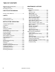
TABLE OF CONTENTS Machine Data Log/Overview.........................1 Table of Contents .........................................2 Receiving Your Unit ......................................4 HOW TO USE THIS MANUAL How to use this Manual. ...............................1-1 SAFETY Safety Instructions ........................................2-1 Hazard Intensity Level ..................................2-3 INSTALLATION & OPERATION Technical Specifications. ..............................3-1 Installation.......
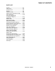
TABLE OF CONTENTS PARTS LIST Frame................................................5-1 Side Panel.........................................5-3 Control Panel ....................................5-5 Engine...............................................5-7 Vacuum Pump ..................................5-9 Water Pump & Chemical Pump ........5-11 Heat Exchanger ................................5-15 Pressure Regulator & Temperature Bypass.........................5-17 Water Box .......................................
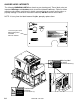
RECEIVING YOUR UNIT DEALER RESPONSIBILITY 8. Waste tank filter and strainer basket. The dealer from whom you purchased this mobile cleaning unit is responsible for the correct installation of this machine. The dealer is also responsible for initial training of your operators and maintenance personnel in the proper operation and maintenance of this unit. 9. 100 ft. of 2” vacuum hose. 10. 1 vacuum hose connector. 11. 100 ft. of 1/4" high pressure hose with quick connects. 12. 50 ft.
HOW TO USE THIS MANUAL The SAFETY section contains important information regarding hazard or unsafe practices of the machine. Levels of hazards is identified that could result in product or personal injury, or severe injury resulting in death. This manual contains the following sections: - HOW TO USE THIS MANUAL SAFETY OPERATIONS MAINTENANCE & SERVICE PARTS LIST The OPERATIONS section is to familiarize the operator with the operation and function of the machine.
IMPORTANT SAFETY INSTRUCTIONS When using this machine, basic precaution must always be followed, including the following: READ ALL INSTRUCTIONS BEFORE USING THIS MACHINE. These symbols mean WARNING or CAUTION. Failure to follow warnings and cautions could result in fatality, personal injury to yourself and/or others, or property damage. Follow these instructions carefully! Read the operator's manual before installing or starting this unit.
DO NOT leave the vehicle engine running while operating this unit. Dangerous Acid, Explosive Gases! Batteries contain sulfuric acid. To prevent acid burns, avoid contact with skin, eyes and clothing. Batteries produce explosive hydrogen gas while being charged. To prevent a fire or explosion, charge batteries only in well ventilated areas. Keep sparks, open flames, and other sources of ignition away from the battery at all times. Keep batteries out of the reach of children.
HAZARD LEVEL INTENSITY The following WARNING LABELS are found on your cleaning unit. These labels point out important Warnings and Cautions which should be followed at all times. Failure to follow warnings and cautions could result in fatality, personal injury to yourself and/or others, or property damage. Follow these instructions carefully! DO NOT remove these labels. NOTE: If at any time the labels become illegible, promptly replace them. Lower front panel decal With warning labels 86186630 PRV NO.
TECHNICAL SPECIFICATIONS ITEM Engine speed Water pump rpm Vacuum pump rpm Water flow rate Water pump pressure Vacuum relief valve Waste tank capacity Console weight Console weight (with waste tank & accessories) TORQUE VALUES Engine rear Vac pump pulley Engine front stub shaft Engine front water pump pulley on stub DIMENSION/CAPACITY 3200 rpm 1400 (idle speed) 1625 rpm 3200 rpm 3.5 GPM (maximum) 1000 PSI (maximum) 13” Hg 60 gallons 500 lbs. (590 lbs.
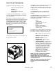
OPERATION INSTALLATION REQUIREMENTS FUEL REQUIREMENTS Prior to starting the installation, first read the ENTIRE "Installation” section of this manual. Since the cleaning unit (with empty waste tank and accessories) weighs approximately 710 pounds (800 lbs. if mounted on water tank), consider the following recommendations before installing this unit. Use unleaded gasoline ONLY. DO NOT use any gasoline additives. We recommend the use of clean, fresh, unleaded gasoline intended for automotive use.
OPERATION CHEMICAL REQUIREMENTS The unit, due to its chemical injection pump design, can be used with a variety of water-diluted chemical compounds (either acidic or alkaline), depending on the job to be done. However, to obtain optimum results with this unit, we recommend using the Prochem line of chemicals. For information on using the cleaning compounds, refer to the chemical manual. WATER REQUIREMENTS Hard water deposits will adversely affect the plumbing and heat exchange systems on this unit.
OPERATION 1 2 3 18 4 17 5 6 16 7 8 15 9 14 10 11 12 13 3-4 86037390 01/10/08
OPERATION 1. VACUUM GAUGE 7. CIRCUIT BREAKERS This gauge indicates in inches of mercury how much vacuum the system is producing at any given time. 2. WASTE PUMPOUT SWITCH/OVERRIDE These serve to protect the circuits from electrical spike and over loads and protects wires from damage and fire. 8. HOUR METER This two-position switch is for activating the waste pumpout device. The hour meter records the number of hours the unit has run. This serves as a time recorder for servicing the machine. 3.
OPERATION 14. PRESSURE CONTROL REGULATOR 16. FLOW METER The pressure regulator sets the pressure of the solution system. This spring loaded valve can be adjusted up or down setting the pressure of the unit by turning the valve clockwise. The pressure is increased or reduced by turning the valve counter clockwise. (This valve must be maintained in accordance with this manuals maintenance table.) 15. SOLUTION OUTLET The solution outlet is the connecting point for the high pressure cleaning hoses.
OPERATION PRESSURE REGULATOR NITROGEN ACCUMULATOR SOLUTION OUTLET OUTLET Y-STRAINER OUTLET CHECK VALVE TEMPERATURE CONTROL VALVE VACUUM EXHAUST RADIATOR-TYPE HEAT EXCHANGER WATER INLET VACUUM INLET BRIGGS & STRATTON VANGUARD ENGINE VACUUM EXHAUST WATER BOX WATER PUMP 145° TEMPERATURE RELIEF VALVE VERY HOT WATER FLOW HOT WATER FLOW WARM WATER FLOW COLD WATER FLOW BYPASS FLOW WASTE TANK ENGINE EXHAUST FLOW VACUUM EXHAUST FLOW VACUUM FLOW 86037390 02/14/07 3-7
OPERATION cleaning process is channeled through a heat exchanger box into the first heater core from the front of the unit. This bypass water may circulate several times through the bypass heat exchanger allowing the water to be pre-warmed. Always wear hearing protection and proper personal protection equipment when operating unit. The next stage of plumbing and heat exchange takes place in the 2nd heater core located in the heater box.
OPERATION The chemical injection system is unique in that it utilizes the pressure spikes generated by the highpressure water pump to move chemical into the main pressure stream. The high pressure spikes move the diaphragm in the chemical pulse pump forcing small amounts of liquid chemical to be moved in a single direction of flow with the aid of two check valves. After reaching the chemical pulse pump the chemicals can either go into a bypass loop to purge air from the system.
OPERATION VACUUM SYSTEM The engine turning a vacuum/blower generates airflow. The air is channeled in one side of the vacuum/blower, compressed and discharged on the opposite side, creating a vacuum. The vacuum is used to do the work necessary for the extraction process. A vacuum nozzle applied to the carpet surface removes moisture, dirt and spent chemicals. These elements are conveyed back to a separating tank utilizing hoses and the force of air.
OPERATION PRE-RUN INSPECTION HIGH PRESSURE HOSE NOTE: Operation of this unit is simple. However, only trained personnel should proceed. Before starting the unit, connect the pressure hose to the outlet connection at the front of the unit. Connect the cleaning tool to the pressure hose. Operate this unit and equipment only in a wellventilated area. Exhaust fumes contain carbon monoxide which is an odorless and deadly poison that can cause severe injury or fatality.
OPERATION PRIMING THE CHEMICAL PUMP 1. Connect water hose to water inlet connection and turn on water supply. 2. Connect cleaning and vacuum hoses to the desired cleaning tool and console. NEVER dispose of waste in storm drains, waterways, or on ground areas. Always dispose of waste in accordance with Local, State, and Federal laws. 4. Pull out engine choke. While holding waste pump out switch in the override position, turn ignition key to start.
OPERATION UPHOLSTERY CLEANING FREEZING PROTECTION Upholstery tool, part #86285260, PRV NO. 78513 If the unit is exposed to freezing weather the water in the unit may freeze, causing SERIOUS DAMAGE to the unit. To avoid this, the following is recommended during the cold weather season. 1. Set temperature as desired and slow down the engine speed to minimize excess heat. 2. Use one (1) “86229980, PRV NO. 80015” spray tip in tool. SHUTDOWN AND DAILY MAINTENANCE 1. Close chemical metering valve. 2.
OPERATION WINTERIZING YOUR UNIT 1. Shut off the water supply. Disconnect the water inlet hose from the front of your console. 2. Connect all high pressure hoses and tools that may have water in them. 3. Start the unit. Open the tool valve until water pressure drops and water stops flowing. 4. Turn off the engine. 5. Fill the water box with approximately two gallons of 100% glycol base anti-freeze. 6. Start the unit. 7. Open the tool valve until anti-freeze begins to come out of the tool.
OPERATION REMOVING ANTI-FREEZE FROM THE UNIT 1. Connect one end of the winterizing loop hose to the solution outlet connection. Place the other end of the loop hose, without the attachment, into an approved container. 2. Start the unit. Allow the anti-freeze to flow into the container until flow stops. 3. Fill the water box with fresh water and repeat step #2. 4. Connect the water inlet hose to the water inlet connection on the console. Turn the water supply on. 5.
MAINTENANCE SERVICE SCHEDULE Engine Daily Vacuum Pump Daily Water Pump Solution Outlet Strainer Vacuum Inlet Filter (In Waste Tank) Vacuum Hoses Automatic Waste Pump Chemical Filter Vacuum Pump Water Box Float Valve Water Pump Inlet Filter Battery Solution Outlet Y-Strainer High Pressure Hoses Pressure Regulator Pressure Regulator Engine Engine Engine Battery Automatic Waste Pumpout Belts/pulleys Water Box Float Valve Seal Engine Fuel Pump Fuel Hose, Fuel Fittings Engine Chemical Valves Heat Bypass Valv
MAINTENANCE SERVICE SCHEDULE Vacuum pump Vacuum Exhaust Heat Exchanger Water Pump Pulley Set Screws & Hub Cap Screws Drive Pulley Drive Pulley Drive Belts Drive Belts Chemical Pump & Check Valves Vacuum Lubrication Lines 250 hrs 500 hrs 500 hrs 500 hrs Engine Heater Core Engine Check Valve (Solution Outlet) Waste Tank Shut-off Float Switch Vacuum pump Nitrogen Accumulator Waste Tank Filters/Strainers Engine Engine 500 hrs 500 hrs 1000 hrs 1000 hrs Monthly Yearly Yearly* Yearly Yearly 3 years 500 hrs 500
MAINTENANCE HEAT EXCHANGER SYSTEM MAINTENANCE KEY CHECKPOINTS Note: Initiation of a planned preventative maintenance program will assure that your unit has optimum performance, a long operating life, and a minimal amount of "down" time. EXTERNAL FUEL PUMP MAINTENANCE The power plant for the unit receives fuel from the main gas tank of your van/truck. An external fuel pump that provides this fuel is located on the underside of the van/truck.
MAINTENANCE DO NOT service this unit while it is running. The high-speed mechanical parts as well as high temperature components may result in severe injury, severed limbs, or fatality. 3. Check the spark plugs every 200 hours. Clean if necessary. Replace the spark plugs every 1000 hours. NOTE: Never sandblast spark plugs. Spark plugs should be cleaned by scraping or wire brushing. NOTE: Use the hour meter as a guide for coordinating the maintenance schedule. 4.
MAINTENANCE VACUUM PUMP Refer to the Vacuum Pump Operation and Service Manual (P/N 86036610, PRV NO. 67-945307) for specific instructions. Lubrication: We recommend that you use AEON PD Synthetic Blower Lubricant in the gear end of the vacuum pump for all operating temperatures. AEON PD is formulated especially for positive displacement blower service to provide maximum blower protection at any temperature. One filling of AEON PD will last a many times longer than a premium mineral oil.
MAINTENANCE WATER PUMP VACUUM PUMP DRIVE BELTS Refer to the Water Pump Operation and Service Manual for specific instructions (P/N 86269900, PRV NO. 67-945621). To tighten the vacuum pump belts: 1. Check the crankcase oil level daily to assure the proper level. Use the illustration as a guide when checking the oil level. If the level has dropped, check for the source of leakage and repair. 2. Use the provided dipstick. Remove red filler cap and insert dipstick.
MAINTENANCE WATER PUMP DRIVE BELT Y-STRAINER (OUTLET) To tighten the water pump belt: 1. Loosen the bolts which hold the water pump mount to base. Inspect the Y-strainer after the first week of running the unit by unscrewing the screen and remove any accumulated debris. Inspect the strainer again at 2 and 4 weeks. 2. Adjust the position of the belt tension adjusting bolt until the proper belt tension is achieved. (1/2" deflection in the center of the belt, halfway between the pulleys).
MAINTENANCE NITROGEN ACCUMULATOR The nitrogen accumulator is pressurized to 250 PSI and must be replaced periodically. The accumulator cannot be repaired or recharged. We recommend replacement every 1000 hours (or yearly) of use. PRESSURE REGULATOR Lubricate the o-rings and bullet every 50 hours. Use o-ring lubricant Part #86265430, PRV NO. 05-008035. For the procedure, see the "General Service Adjustments” section in this manual for details.
MAINTENANCE SERVICE GENERAL ADJUSTMENTS Tight wrap On spring USE EXTREME CAUTION while servicing while machine is running. The high-speed mechanical parts as well as high temperature components may result in severe injury, severed limbs, or fatality. ENGINE SPEED Use 5/16 Allen Wrench to remove This unit uses a factory installed Briggs & Stratton engine governor. The engine speed is adjusted using the “T” handle throttle control. Pushed in the engine is at idle speed (1400 rpm).
MAINTENANCE PACKING NUT ADJUSTMENT FOR CHEMICAL METERING BYPASS AND CHEMICAL SELECTOR VALVES Examine the packing nut on the metering and selector valves for proper tension every 200 hours. When turning the knob, there should be a small amount of resistance. If not, slightly tighten the packing nut. DO NOT over tighten. Keeping the valve packings properly adjusted will eliminate possible leakage from the valve stem and add to overall valve life. Remove knob by loosening set screw to access packing nut.
MAINTENANCE PROBLEM CAUSE SOLUTION Water supply is turned off or the float valve is stuck or improperly adjusted. Water pump inlet supply line is plugged or drawing air. Improper engine speed Loss of water pump pressure. With the cleaning tool open, the water pressure gauge reads below the normal operating pressure. Pressure regulator o-rings are dry. Pressure regulator has worn o-rings Pressure regulator is dirty, stuck open, or improperly adjusted. Low pump volume.
MAINTENANCE PROBLEM Loss of vacuum While cleaning, the vacuum is not up to specification. Engine RPM is normal. Excessive Vacuum Loss of chemical With the cleaning tool valve open, no chemical CAUSE SOLUTION Examine the tubing between the vacuum Vacuum gauge is giving an improper relief valve and the vacuum gauge and reading. remove any blockage. Vacuum hose(s) is damaged, Inspect hose(s), repair or replace. causing a suction leak. Waste tank gaskets not sealing Inspect the gasket.
MAINTENANCE PROBLEM CAUSE SOLUTION External leak in chemical piping Chemical flow meter indicates flow with the tool valve closed Outlet check valve is full of debris or damaged, not allowing it to close properly Chemical pump diaphragm is ruptured Internal leak in chemical valve causing continual flow through prime tube returning to container. Main circuit breaker on the control panel has been tripped. Loose or corroded battery. Engine will not start The engine does not turn over Dead battery.
MAINTENANCE PROBLEM Engine stops running While doing normal cleaning, the engine stops running Excessive heating CAUSE SOLUTION Engine is out of gasoline Add gasoline to the fuel tank. Waste tank is full Empty waste tank. After inspecting the unit to determine the cause of the tripped circuit breaker, press the reset button. Replace fuel pump. Check switch for proper operaton. Replace as necessary. Refer to the Briggs & Stratton Engine Operation and Maintenance Manual.
FRAME 19 1 2 16 17 18 3 4 20 11 23 21 22 4 5 3 8 4 15 14 8 12 10 8 6 7 9 5-1 86037390 02/14/07 8 3 13 3 4
FRAME REF 1 2 3 4 5 6 7 8 9 10 11 12 13 14 15 16 17 18 19 20 21 22 23 PART NO. 86191570 86046100 86010780 86274750 86054520 86177040 86176170 86270330 86179620 86047940 86279400 86045290 86273180 86043810 86275460 86193220 86189660 PRV NO.
SIDE PANEL 1 2 11 10 5 9 4 3 8 6 7 5-3 86037390 02/14/07
SIDE PANEL REF 1 2 3 4 5 6 7 8 9 10 11 PART NO. 86046080 86180370 86010780 86270330 86181360 86188210 86179710 86274750 86180700 86178700 86186820 PRV NO.
CONTROL PANEL-UPPER 2 1 3 7 5 8 30 9 33 6 7 11 4 10 12 32 31 18 14 13 27 26 15 16 24 22 25 23 29 21 28 20 5-5 19 86037390 01/12/08 17
CONTROL PANEL-UPPER REF 1 2 3 4 5 6 7 8 9 10 11 12 13 14 15 16 17 PART NO. 86195050 86177660 86247720 86136310 86297070 86180140 86181300 86270920 86274290 86279470 86180380 86180350 86190830 86246890 86270330 86010780 86274750 PRV NO.
ENGINE 26 17 17 6 1 2 25 23 5 4 3 28 5 27 24 22 7 21 8 20 9 19 12 16 11 18 14 15 13 9 10 17 5-7 86037390 02/14/07
ENGINE REF 1 2 3 4 5 6 7 8 9 10 11 12 13 14 15 16 17 PART NO. 86174440 86180090 86180720 86190960 86279130 86274690 86190570 86005750 86278830 86274900 86183600 86190550 86174450 86049230 86175030 86191030 86273440 PRV NO. QTY DESCRIPTION 42-902005 1 B&S CARTRIDGE AIR CLNR 394-018 42-902006 1 ELEMENT (OUTER), AIR CLEANER 32056 1 ENG, 18HP 2CYCL, B&S, CLR/CLN 790833 1 PULL, ENG, 18HP, B&G 87083 2 WASHER, 5/16 SPLIT LOCK PLTD 70258 2 SCR, 5/16-18 X 1.
VACUUM PUMP 20 11 19 21 18 16 23 17 3 2 1 4 6 5 15 7 9 8 10 11 22 SUPPLIED 12 14 5-9 13 86037390 08/20/08 WITH PUMP
VACUUM PUMP REF 1 2 3 4 5 6 7 8 9 10 11 12 13 14 15 16 17 18 19 20 21 22 23 PART NO. 86191370 86188500 86177010 86184490 86049240 86191030 86175030 86273440 86185340 86005770 86279510 86045260 86270320 86273400 86162540 86193230 86180600 PRV NO. QTY DESCRIPTION 41-905024 1 PUMP, 3LVLTHC 54-501593 1 NIP, VAC EXH OUTLET 03-000112 2 CLAMP, HOSE #48 09-805478 1 HOSE, VAC 2.88 X 2.
WATER PUMP & CHEMICAL PUMP TO WATER BOX 2 3 6 7 5 TO FRONT ENGINE PULLEY 4 9 28 26 10 27 22 8 11 15 12 18 16 25 19 14 21 20 16 23 17 18 19 1 39 20 36 35 31 32 38 37 35 36 33 34 5-11 29 20 24 30 13 86037390 01/25/08
WATER PUMP & CHEMICAL PUMP REF 1 2 3 4 5 6 7 8 9 10 11 12 13 14 15 16 17 PART NO. 86177320 86177020 86181370 86180230 86180410 86190670 86180340 86190520 86190990 86191070 86273440 86049240 86137310 86190540 86276130 86278830 86005750 PRV NO.
WATER PUMP 5 1 2 11 10 7 4 3 9 8 6 9 8 5-13 86037390 02/14/07
WATER PUMP REF 1 2 3 4 5 6 7 PART NO. 86176520 86189200 86195580 86192260 86189210 86186090 86190600 PRV NO. QTY DESCRIPTION 42-809238 1 CAP, OIL FILLER 42-809239 1 O-RING, OIL FILL CAP 42-809249 1 WASHER, KEYHOLE M18 42-809409 1 SEAL, OIL CRANKCASE 42-809394 2 O-RING, BEARING CVR 42-809410 1 KIT, SEAL 42-809408 1 PLUNGER 8 86286260 66-950441 - 9 10 11 86190560 42-809404 86181800 43-807063 86181970 42-902380 2 1 1 KIT, VLV CAT 3CP1140, 33258 SERIAL NO.
HEAT EXCHANGER 10 9 4 3 5 2 6 30 11 1 7 6 5 13 4 8 29 SST CORE 26 27 12 14 2 26 25 22 COPPER CORE 14 28 20 19 24 23 18 17 16 15 5-15 86037390 02/14/07
HEAT EXCHANGER REF 1 2 3 4 5 6 7 8 9 10 11 12 13 14 15 16 17 18 19 20 21 22 23 24 25 26 27 28 29 30 PART NO. 86056820 86278830 86192110 86274750 86010780 86270330 86029430 86181810 86177000 86059020 86051550 86047250 86049190 86177700 86180220 86181400 86182190 86190520 86187210 86047260 86030280 86189730 86181850 86005650 86279130 86275760 86181330 86043150 86010740 PRV NO.
PRESSURE REGULATOR & TEMPERATURE BYPASS 19 12 1 16 15 20 2 18 9 3 13 3 4 12 30 6 11 10 5 29 7 8 OUTER SEAT CHECK VALVE DETAIL INNER SEAT 22 23 9 CAP STEM 24 SPRINGS BODY 25 26 21 27 28 PRESSURE REGULATOR DETAIL 5-17 86037390 02/14/09
PRESSURE REGULATOR & TEMPERATURE BYPASS REF 1 2 3 4 5 6 7 8 9 10 11 12 13 14 15 16 17 PART NO. 86173460 86187250 86188110 86191630 86180040 86188390 86192210 86195030 86180360 86180410 86311640 86177660 86180450 86177680 86279400 86275460 86278970 18 19 20 21 22 23 24 25 26 27 28 29 30 86002450 86195050 86180420 86186040 86189230 86192390 86194250 86190910 86193260 86189270 86176350 86189260 86190180 PRV NO.
WATER BOX 31 25 26 27 30 29 28 1 2 24 3 22 23 19 21 4 10 20 5 19 18 6 17 7 16 8 15 14 13 3 9 12 11 5-19 86037390 02/14/07
WATER BOX REF 1 2 3 4 5 6 7 8 9 10 11 12 13 14 15 16 17 18 19 20 21 22 23 24 25 26 27 28 29 30 31 PART NO. 86273410 86010780 86270330 86048360 86187820 86174540 86177660 86195340 86058750 86181150 86181370 86180230 86274750 86188180 86193440 86272720 86270770 PRV NO.
WASTE TANK 1 2 13 4 3 5 6 7 14 8 13 9 8 12 10 12 11 5-21 86037390 02/14/07
WASTE TANK REF 1 2 3 4 5 6 7 8 9 10 11 12 13 14 - PART NO. 86049690 86043190 86182710 86193430 86058600 86180340 86277830 86279510 86249550 86005770 86193870 86190530 86186860 86273020 86264850 PRV NO. QTY DESCRIPTION 790652 1 LID, 60G WST TNK 56-501793 1 ASSY, BSKT.
HOSE ACCESSORIES 1 2 3 2 7 4 5 10 6 11 12 9 8 17 14 13 18 19 15 21 20 16 5-23 86037390 02/14/07
HOSE ACCESSORIES REF 1 2 3 4 5 6 7 8 9 10 11 12 13 14 15 16 17 18 19 20 21 PART NO. 86180980 86178640 86184510 86247680 86002450 86005580 86184530 86184520 86182800 86194990 86189240 86189250 86188210 86184570 86179630 86184620 86002450 PRV NO.
BATTERY-FLOOR MOUNT 2 1 10 3 4 5 9 6 7 8 5-25 86037390 05/03/08
BATTERY-FLOOR MOUNT REF 1 2 3 4 5 6 7 8 9 10 PART NO. PRV NO. QTY DESCRIPTION 86273780 70015 2 SCR, 1/4-20 X 3/4 HHCS SS NP 86005680 57047 2 NUT, 1/4-20 HEX NYLOCK 86174580 36-900056 1 BATTERY 86012060 1 BOX, BATTERY, MODIFIED 86273190 00-000132 4 SCR, 1/4-20 X 1-1/2 HXHD 86270330 02-000066 8 FLATWASHER, 1/4 86010780 87162 8 WASHER, 1/4 SPLIT LOCK PLTD 86270770 57006 8 NUT, 1/4-20 HEX 86309890 1 BRKT, BATTERY BOX MTG 86011470 4 BOLT, ELEVATOR, 1/4-20 X 1 86037390 05/03/08 SERIAL NO.
AUTOMATIC PUMPOUT-OPTIONAL 11 17 19 16 6 10 7 18 10 1 4 5 5 3 7 2 5 13 6 5 14 4 3 8 5-27 9,12,15 86037390 02/14/07
AUTOMATIC PUMPOUT-OPTIONAL REF 1 2 3 4 5 6 7 8 9 10 11 12 13 14 15 16 17 18 19 PART NO. 86274150 86273190 86270770 86010780 86270330 86177050 86280680 86184780 86176420 86181430 86181440 86195820 86175720 86188970 86162270 86191380 86174260 86195860 86195910 PRV NO.
AUTOMATIC PUMPOUT-OPTIONAL 26 36 23 15 1 24 16 37 19 22 11 22 11 17 27 26 3 29 30 32 25 20 9 34 31 33 18 5 14 13 28 4 8 7 35 6 21 39 10 8 21 38 21 10 12 2 21 5 5-29 86037390 05/22/08
AUTOMATIC PUMPOUT-OPTIONAL REF 1 2 3 4 5 6 7 8 9 10 11 12 13 14 15 16 17 PART NO. 86273250 86178820 86192020 86273550 86273280 86005810 86010780 86279470 86024840 86174520 86024850 86193250 86174700 86179530 86187870 86182540 86182550 18 19 20 21 22 23 24 25 26 27 28 29 30 31 32 33 34 35 36 37 PRV NO.
WAND-TITANIUM SIX JET-OPTIONAL 9 11 22 3 3 9 23 18 18 24 20 14 21 5 2 17 4 8 10 15 16 13 12 32 1 19 25 7 30 29 33 26 27 35 31 28 34 5-31 86037390 02/14/07
WAND-TITANIUM SIX JET-OPTIONAL REF 1 2 3 4 5 6 7 8 9 10 11 12 13 14 15 16 17 PART NO. 86273310 86192030 86006680 86270990 86264910 86184270 86247680 86190180 86177650 86177710 86005580 86193490 86194450 86195570 86177860 86177870 PRV NO.
WAND-QUAD JET-OPTIONAL 27 28 29 30 31 32 33 14 9, 10 16 17 34 8 7 12 11 4 13 6 5 2 15 3 14 1 25 21A, 21B 26 19, 20 23, 23A, 23B 19, 24 5-33 86037390 01/25/08
WAND-QUAD JET-OPTIONAL REF 1 2 3 4 5 6 7 8 9 10 11 12 13 14 PART NO.
WAND- TRI JET- OPTIONAL 25 26 27 29 30 28 31 16 14 17 9, 10 32 8 7 12 6 5 4 11 13 15 3 2 1 24 23 20, 21, 22 5-35 86037390 02/14/07 19, 19A, 19B
WAND- TRI JET-OPTIONAL REF 1 2 3 4 5 6 7 8 9 10 11 12 13 14 PART NO. 86285520 86285510 86285530 86005580 86177860 86195570 86193490 86177870 86247680 86280020 86194650 86192030 86270990 86174120 86177650 86183970 86265730 PRV NO.
STAIR TOOL-OPTIONAL 16 17 18 20 19 21 22 2 3 23 4 6 5, 5A 7 8 9, 10 11 12 14 13 15, 15A 5-37 86037390 02/14/07
STAIR TOOL-OPTIONAL REF 1 2 3 4 5A 5B 6 7 8 9 10 11 12 13 PART NO. 86285350 86285290 86198080 86198170 86265730 86183710 86184000 86194410 86273310 86177650 86192030 86270990 86174120 86247680 86005580 PRV NO. DESCRIPTION 78519 78521 OPEN 52-501576 52-501577 04-000053 10-805330 10-805397 17-803002 00-000282 12-800060 00-000317 57090 61-950496 56015 56012 TL, STAIR, LNG, TM DJ (80015) TL, STAIR, SHT, TM (80015) BODY, WD HDL PORT HOLD DOWN, WD HDL PORT TIE, CABLE 8” WHT HOSE, 3/16X14.
UPHOLSTERY TOOL-OPTIONAL 20 21 22 23 27 24 25 28 26 29 30 37 31 8 34 36 33 32 7 6 35 4 11 3 5 1 9 10 12 14 16 2 13 18 15 19 17 3 5-39 86037390 02/14/07
UPHOLSTERY TOOL-OPTIONAL REF DESCRIPTION SERIAL NO. FROM PRV NO. QTY 1 2 3 4 5 6 7 8 9 PART NO.
SHELF ASSEMBLY-OPTIONAL 16 4 3 17 2 1 4 3 2 4 15 3 2 6 2 3 5 4 7 10 8 2 5 4 2 9 12 2 10 14 4 10 2 5 OVERALL DIMESNION: 41-1/2" TALL 50-1/8" WIDE 57" WIDE (WITH TOOL HOLDERS) 7-7/8" DEEP 10 2 12 DIMESIONAL DATA 50 1/8 7 5 1 5-41 3 86037390 02/14/07 11
SHELF ASSEMBLY-OPTIONAL REF 1 2 3 4 5 6 7 8 9 10 11 12 13 14 15 16 17 - PART NO. 86285410 86192680 86270330 86010780 86274760 86274750 86175710 86175730 86198090 86285120 86270620 86024890 86278840 86021920 86186850 86183180 86183170 86179350 PRV NO.
WATER TANK, DUAL WITH DEMAND PUMP-OPTIONAL 1 1 4 3 2 2 3 4 13 5 12 13 6 7 9 9 8 11 6 7 7 10 7 8 TO DEMAND PUMP 8 OVERALL DIMNSION: 32-1/2" TALL 62-5/8" WIDE 15-1/2" DEEP 14 5-43 86037390 02/14/07
WATER TANK, DUAL WITH DEMAND PUMP-OPTIONAL REF 1 2 3 4 5 6 7 8 9 10 11 12 13 14 15 - PART NO. 86041730 86041710 86048310 86279510 86010790 86277830 86176400 86180170 86181370 86177020 86280590 86194120 86043320 86030990 86190500 86190170 86005770 86285190 PRV NO.
WATER TANK-DEMAND PUMP-OPTIONAL 3 2 4 1 11 6 5 4 10 4 9 12 13 16 16 8 7 5-45 8 86037390 02/14/07
WATER TANK - DEMAND PUMP-OPTIONAL REF PART NO. PRV NO.
AUXILIARY WATER TANK WITH PUMP 12 21 33 28 24 9 29 15 32 22 39 2 40 23 1 11 37 8 27 17 38 20 18 40 25 10 40 5 13 31 16 19 3 6 4 26 30 35 36 7 34 4 14 2X 18.7 4X Ø.406 MOUNTING DETAIL 2X 16.8 30.0 WIDE Vehicle Floor 34 58.6 LENGTH 30.
AUXILIARY WATER TANK WITH PUMP ` REF 17 PART NO.
AUXILIARY WATER TANK-OPTIONAL 27 26 24 25 1 3 4 21 6 23 7 8 2 9 20 16 19 10 18 20 19 11 5 21 18 DEMAND PUMP SUBASM 12 13 16 17 16 15 14 5-49 86037390 09/06/07
AUXILIARY WATER TANK-OPTIONAL REF 1 2 3 4 5 6 7 8 9 10 11 12 13 14 15 16 17 18 19 20 21 22 23 24 25 26 27 PART NO. 86176400 86191600 86180170 86181360 86177020 86280100 86179710 86047580 86030970 86278830 86279130 86006750 86050960 86176420 86195820 86181320 86280060 PRV NO.
HOSE REEL-OPTIONAL OVERALL MOUNTING DETAIL 1 47" TALL 44-1/2" DEEP Vehicle Floor 21 23 22 24 25 17 13 14 15 5 6 16 8 13 14 2 7 12 15 16 15 3 9 2 5 3 13 6 10 11 12 10 14 7 9 4 5-51 86037390 09/06/07 8
HOSE REEL-OPTIONAL REF PRV NO. QTY 1 2 3 4 5 6 7 8 9 10 11 12 13 14 15 16 17 PART NO.
WIRING DIAGRAM 5-53 86037390 09/06/07
86037390 09/06/07 HEAT EXCHANGER 86184410 (28") PRV NO. 790420 86183470 (23") PRV NO. 10-805204 86192870 (8") PRV NO.10-805355 86282470 (19") PRV NO. 790725 86177060 (2) PRV NO. 03-000246 86184390 (20") PRV NO. 790418 86183600 (10") PRV NO. 10-805291 86183530 (68-1/2") PRV NO. 10-805271 1 86048980 (36") PRV NO. 09-805341 86280400 (7.25") PRV NO. 09-805351 TO WASTE TANK 86283010 (45") PRV NO. 09-805567 86282770 PRV NO. 51372 86183480 (15") PRV NO.