
Instruction manual


OPERATIONS for E5CK (Continued):
PID Tuning:
The Digital Temperature Controller incorporates the capability of automatically tuning
the PID parameters (Auto-Tuning) to fit the characteristics of the process. The optimum
PID parameters are automatically set by forcibly changing the Manipulated Variable
(MV) to calculate the characteristics (limit cycle method) of the control target.
Depending on the auto-tune level selected, AT-1 or AT-2, the controller will run this test
at either 40% or 100% of the actual Process Set Point. When the auto tuning is
complete, the appropriate PID tuning parameters will be automatically installed into the
non-volatile memory of the temperature controller.
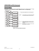
The PID Tuning Process can be started by adjusting the (At) parameter.
9. Turn on water supply and set the desired water flow.
10. Set the Process Temperature Set point to the desired value.
(See OPERATIONS; Changing Primary Set point,).
11. Press the Display Key
for a minimum of one second to enter the level select
mode.
12. Press the up or down arrow key to select the desired level. (Level 1 for Auto
Tune adjustment).
13. Press the Display Key
for a minimum of one second to enter the selected
level mode menu.
14. Press the Display Key
for less than one second to cycle through the selected
level mode menu until (At) is shown on the upper display.
15. Press the up or down arrow key to adjust the (At) value to the desired setting of
(AT-2).
16. Press the Display Key
for a minimum of one second to once again enter the
level select mode.
17. Press the up or down arrow key to select the desired level. (Level 0 for normal
control operation). The “AT” LED will flash during the Auto-Tune cycle.
18. Turn the ENABLE HEATER switch past the ON position to the RESET position,
then release the switch, which will move to the ON position. If all criteria for the
various safety devices have been met, the heater will begin to heat.
19. When the process is complete, the “AT” LED will stop flashing. The appropriate
PID tuning parameters are now installed and retained in the non-volatile memory.
M-45-02 TYTAN Manual
Revision - Date: 01 – 11/16/07
38