
Installation manual


CM-02-001
TYTANu DI Water Heater
O.I. 6/27/03 Installation, Operation and Maintenance Manual
ECO page 11
3.4 Electrical Connections:
3.4.1 Incoming Power Connections:
TYTANu DI Water Heaters are designed to operate on 4 or 5 wire electrical supplies (3 power wires, 1 ground wire). All
electrical connections should conform to local electrical codes and/or NFPA 70/79.
1) Check the system tag located on the equipment for Power Requirements. Do not operate this heater on Voltages other
than the Voltage rating on the system tag.
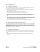
2) Remove lower front cover of the cabinet by loosening all cover mounting screws.
3) Fuse the incoming line for the rated amperage using an approved electrical disconnect box.
4) Supply power to the unit from the electrical panel into the cabinet through the opening at the “service entrance”. This
opening will need to be made by the customer. Ensure that the wire has sufficient amp capacity to safely carry the power
load.
5) Connect the leads from the incoming power line to the appropriate terminals (reference the Electrical Schematic) making
sure not to disturb existing wiring. Use care that no loose strands of wire are exposed out of the Terminal Block. Torque all
wires to the specified ratings located on the wiring diagrams and component labels.
6) Grounding is done internally from the Incoming Power Strip. Reference the wiring diagram in the appendix.
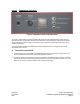
3.4.2 RS-232 / RS-485 Serial Communication Interface (Optional):
In units supplied with the RS-232 / RS-485 serial communication interface, the Temperature Controller is equipped with RS-232 /
RS-485 Serial Communication capability for use with a customer-supplied host computer. If this option is used, all temperature
and related parameters can be monitored or altered from the host computer. On standard units, the DB-9 receptacle(s), labeled
REMOTE COMMUNICATIONS, is(are) located at the rear (or bottom) of the cabinet. An independent serial cable should be
installed between the host computer and the DB-9 receptacle.
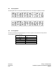
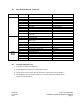
3.4.3 Customer Interface Plug (Optional):
The Auxiliary Equipment Interface Plug is used for communication between the Process Controller and customer-supplied
devices. The interface plug is located on the rear (or bottom) of the Cabinet enclosure. Refer to dimensional drawings in the
appendix.
Ø Reference the electrical drawings supplied in the appendix for options provided and proper interface connector pin
orientation.