TYTANTM Electric Water Heater Installation Manual Please supply your in-line heater model and serial number when ordering spare parts or requesting technical assistance.
Table of Contents Related Documents ......................................................................................................................................................................3 Section 1: Introduction...........................................................................................................................................................4 1.1 TYTAN DI Water Heater model number designation.............................................................................
RELATED DOCUMENTS The following documents are to be used in conjunction with this manual: ANSI/NFPA70 – National Electric Code®, latest edition. To be used in conjunction with electrical service, wire sizing, routing and protection. SEMI S2 – Semiconductor Equipment Safety Guidelines, latest edition. To be used in conjunction with safe operation, access and decommissioning procedures. OMRON E5CK INSTRUCTION MANUAL – Latest Edition.
Section 1: Introduction The Process Technology TYTANu DI Water Heater is designed to accommodate normal fluctuations in flow and process temperatures while providing a safe, energy efficient heater. The heating elements have a durable low watt density design which gives the element a long service life while maintaining a high flow capacity. The heating elements and wetted surfaces of the DI Water Heater are manufactured from either Titanium or Stainless Steel as ordered by the customer.
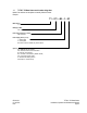
1.1 TYTANu u DI Water Heater model number designation: Model / Part numbers are descriptive and usually follow this format.
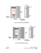
Figure 1: Dimensional Drawing, 12kW-48kW Units. Figure 2: Dimensional Drawing, 72kW Unit. CM-02-001 O.I.
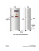
Figure 3: Dimensional Drawing, 96kW-144kW Units. CM-02-001 O.I.
1.2 Performance Data: The TYTANu DI Water Heater is designed for inline heating of DI water. It will perform both as a recirculating heater, and as a one-pass heater. The TYTANu DI Water Heater is designed to provide a specified temperature increase at a given flow rate. Table 1 shows the maximum temperature increase (∆T) that can be achieved for continuous flow conditions at the specific heater power ratings varying from 24kW to 144 kW (Higher wattage systems available upon request).
1.3 Safety Network: (Continued) 2. High Limit (HSP1). This high-temperature alarm setting is set at 248°F (120°C). If this temperature is detected at this sensor. the controller will disengage the main load contactor and sound the audible alarm. This will require a manual reset of the heater once the overheat event has been corrected. Pressure Relief Valve: The heating columns are protected from pressures over 100 PSI (6.
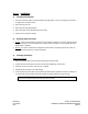
Section 3: 3.1 Installation: Uncrating and Inspection: 1) The TYTANu DI Water Heaters are crated and shipped in an upright position. If the unit is not upright, return the crate to an upright position and inspect carefully. 2) Remove front side of the crate. 3) Remove the protective packaging material. 4) Remove the unit from crate by grasping the sides of the cabinet. 5) Inspect the unit for any apparent damage. 3.
Electrical Connections: 3.4 3.4.1 Incoming Power Connections: TYTANu DI Water Heaters are designed to operate on 4 or 5 wire electrical supplies (3 power wires, 1 ground wire). All electrical connections should conform to local electrical codes and/or NFPA 70/79. 1) Check the system tag located on the equipment for Power Requirements . Do not operate this heater on Voltages other than the Voltage rating on the system tag.
Section 4: Temperature Controller: Figure 4: Temperature Controller and Control Panel. The TYTANu Heating System incorporates a self-tuning, PID microprocessor based, digital temperature controller with a set high temperature alarm. The PID feature enhances the controller's ability to reach and maintain a constant process temperature. The self-tuning feature enables the controller to measure the process characteristics and indicate desired values, which can be displayed on LED displays.
4.1.1 Display Symbols: The following tables show the correspondence between symbols shown on the displays and alphabetic characters. 4.1.2 Selecting Modes: The modes are selected by pressing the Display Key for one second or greater. The up and down arrow keys allow the movement between modes in the top display. CM-02-001 O.I.
4.1.3 Mode Parameter Settings: Omron E5CK temperature controller: When in the selected mode press the Display Key for less than one second to switch parameters. Mode Level 0 Level 1 Level 2 Parameter r–S At AL–1 AL–2 P i D CP SPrU SPrt mU – S mU – E OL–H OL–L OrL inF ALH1 ALH2 ALH3 inSH inSL CM-02-001 O.I.
4.1.3 Mode Parameter Settings: (Continued) Mode Parameter in–t d –U init OUt1 OUt2 SUb1 ALt1 AL1n ALt2 AL2n OrEv Setup Option (RS 232) (RS 485) 4.1.
4.1.5 High Alarm: The Digital Temperature Controller incorporates an independent alarm. The High Process Temperature Alarm prevents heater operation above a preset maximum temperature that may harm the process and potentially the tank material. If the process temperature exceeds the preset high alarm value, the heater will be disengaged. The temperature controller will activate once the process temperature exceeds the set point by the preset value. 1.
4.1.7 Measuring PID Constants: (Continued) 8. Start heater(s) via the Off-On-Reset switch. 9. When the process is complete, the “AT” LED will stop flashing. The appropriate PID tuning parameters are now installed and retained in the non-volatile memory. Note: To abort auto tuning, the operator must reset the "AT" parameter to "OFF". This leaves the unit in an On/Off heat control state in auto operation at the displayed set point. All PID values are set to "0". 4.1.
4.2.1 Programming: (Continued) Caution: When the enclosure door is open, be careful not to touch the electrified components inside. To avoid shock hazard, this procedure should only be performed by qualified personnell. 3 ) Identify the over-temperature controller, tagged 1SLC. 4 ) Press the Index key ( ) twice until “SP2” is highlighted. 5 ) Using the “p” or “q” buttons, adjust the SP2 value until it is 18°F (10°C) higher than the set point on the temperature controller.
5.2 5) System Start-Up: (Continued) Engage the "CONTROL POWER" switch on the control panel. At this time the temperature controller and all optional displays will come on. Note: Temperature controller set point should be set to "0" at this time to prevent accidental heater engagement during calibration procedures. Reference temperature controller section if required. 5.3 Normal Operation: Normal operation of the TYTANu DI Water Heater will consist of the following steps: 1) Initiate water flow.
Service Policy: 6.2 Process Technology supports its product line with a strong technical support and field service program. If your TYTAN™ DI Water Heater fails to perform properly, follow the outlined steps for resolution. Note: If the unit was damaged in transit, contact the freight carrier directly. Process Technology is not responsible for shipping damage. 1) Verify connections and program parameters. 2) Contact the Process Technology Technical Service Group.
6.3 Warranty: All products and components not manufactured by Process Technology will carry the original manufacturer's warranty, copies of which are available upon request. Process Technology makes no warranty or representation, expressed or implied, with respect to the products not manufactured by Process Technology. Process Technology industrial products are warranted against defects in materials and workmanship for a period of one year from date of shipment and this is applied on a pro-rated basis.