
Installation Guide
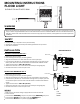

SQUARE POLE MOUNTING: FIG. 1
MOUNTING INSTRUCTIONS
FLOOD LIGHT
SUITABLE FOR WATTAGES: 200W
ELECTRICAL SHOCK HAZARD
before installing the equipment.
WARNING
SAFETY
INSTALLATION
WIRING
Make sure that the mains voltage is appropriate and conforms with the
luminaire driver.
Connect fixture GROUND (green) wire to power supply
GROUND (green) wire.
Connect fixture WHITE wire to power supply
(-) COMMON wire.
Connect fixture BLACK wire to power supply
(+)LINE wire.
(+)LINE
(-) COMMON
GROUND
DRILLING DETAILS
Disconnect the Electrical supply power at the service panel (fuse or circuit breaker box). Failure to do so could result in serious
injury or death. Only qualified electricians should install this fixture and the installaon MUST conform to the Naonal Electrical
Code Part I and all local codes and ordinances. Ensure that only proper tools, materials, and equipment are used to complete the
installaon.
• Proper grounding is required to ensure personal safety.
• Servicing this equipment should be performed
by qualified service personnel.
• Save these instrucons.
• Remove the pole’s top cover.
• Drill mounting holes into pole, see drilling details.
• Align the two extension arm holes with the holes in the square pole.
• Insert the two 5/16-18x1-1/2” hex head bolts through the arm, pole and into the
bolster plate. Each bolt must have flat washer and lock washer added as shown.
• Tighten the two bolts to 140 in-lbs (16 N m)
• Remove the extension arm’s cover and connect leads (see wiring diagram).
• Re-attach extension arm cover and pole cover.
ROUND POLE MOUNTING: FIG. 2
• Remove the pole’s top cover.
• Drill mounting holes into pole, see drilling details.
• Align the two extension arm holes with the holes in the adapter and round pole.
• Insert the two 5/16-18x1-1/2” hex head bolts through the arm, adapter, pole and
into the bolster plate. Each bolt must have flat washer and lock washer added as
shown.
• Tighten the two bolts to 140 in-lbs (16 N m)
• Remove the extension arm’s cover and connect leads (see wiring diagram).
• Re-attach extension arm cover and pole cover.
FIGURE 1
Bolster Plate
Cover
Cover
FIGURE 2
Bolster Plate
Adapter
73.3mm
[2.88”]
534.9mm
[21.059”]
345mm
[13.583”]
345mm
[13.583”]