
Installation Instructions
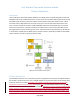
Table Of Contents

Pro1 Wireless Thermostat and Base Module
Theory of Operation
Page 2 of 2
but may be reduced as much as 40dB in steps of 5dB. channel 0 (915.0 MHz). Once setup is complete
and the thermostat is “paired” to the base module, the frequency used will change to one of 4 pre-
defined channels that is determined by the base module’s unique ID (915.1, 915.2, 915.3 or 915.4 MHz).
The frequency channel does not change during normal operation.
During setup, a number of transmission events are triggered by the user activating push buttons on the
Thermostat. The base module acknowledges each transmission in a form of wireless handshaking
between the thermostat and base module. Once set up is complete, the system will enter normal
operation.
Under normal operation, the thermostat will send environmental data (temperature, humidity, etc.) to
the base module every second. Immediately after a transmission event from the thermostat, the base
module is allowed to transmit data back to the thermostat if required. Since the thermostat must
initiate all communications it may enter a low power sleep mode between transmission events.
The thermostat also contains motion detector and light sensor circuitry to determine if a room is
occupied. In some cases, such as when motion is detected or a light transition occurs, the thermostat
may transmit additional data to the base module between the 1 second updates. Software filtering is
included to prevent continuous transmissions to the base module under these circumstances.
802.11 (WiFi) Wireless Link
The base module contains an Azurewave AW-CU300, certified WiFi module that operates in the 2.4 GHz
ISM band. The module includes an integrated, printed circuit board antenna. The included u.fl connector
is not used. Additional information about the module can be found at the following link.
https://fccid.io/ANATEL/01874-16-03657/Manual_AW-CU300/5044DF1A-B9FB-49E3-9787-30161740DBFC
Host Microcontroller
Both the thermostat and the base module contain a host microcontroller operating from an internal
oscillator. The host microcontroller communicates to the S2-LP 915 MHz transceiver using a SPI
interface. For the base module, the host microcontroller communicates to the AW-CU300 WiFi module
using a UART interface.
Models
Pro1 desires to create multiple models for the thermostat and base module. All models are required to
have the 915 MHz wireless link. In some cases, there may be models that do not have the WiFi module.
Model derivations will consist of depopulating digital circuitry such as the humidity sensor circuitry,
motion sense circuitry, light sense circuitry, user push button inputs, etc. It is Pro1’s goal to test the fully
populated model (T755WO) as a worst case sample then add model derivatives with features removed
as approved models to the report.