
Install Instructions
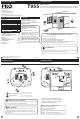
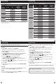

Getting to know your thermostat
Glow in the dark light button
Fan Key
System Key
Setpoint buttons
Menu button
LCD Display
1
2
3
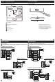
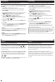
Gently slide a screwdriver into the
bottom edge of the badge. Gently turn
the screwdriver counter clockwise. The
badge is held on by a magnet in the well
of the battery door. The badge should pry
o easily. DO NOT USE FORCE.
About The Badge
All of our thermostats use the same universal magnetic badge. Visit the
company website to learn more about our free private label program.
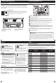
Private Label BadgeThermostat Quick Reference
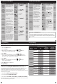
Wiring Diagrams Wiring Diagrams
Typical 2H/2C System: 1 Transformer Typical 2H/2C System: 2 Transformer
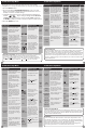
Typical 3H/2C or 2H/1C Heat Pump System
Typical Heat-Only System
Typical Heat Only System With Fan
Typical Cool-Only System
HEAT RELAY
RC
RH
Y
C
W/E
G
C
R
L2
L1(HOT)
FAN RELAY
HEAT RELAY
RC
RH
Y
C
W/E
G
C
R
L2
L1(HOT)
FAN RELAY
COMPRESSOR
RELAY
C
R
L2
L1(HOT)
RC
RH
Y
C
G
Power supply
Factory-installed jumper. Remove only when installing on 2-transformer systems
Use either O or B terminals for changeover valve
Optional 24 VAC common connection when thermostat is used in battery power mode
W/E
RC
RH
Y
C
W/E
G
W2
Y2
COMPRESSOR
RELAY
FAN RELAY
AUXILIARY
HEAT RELAY
COMPRESSOR
RELAY 2
COOL CHANGE
OVER VALVE
HEAT CHANGE
OVER VALVE
C
R
L2
L1(HOT)
REMOVE JUMPER
RC
RH
Y
C
W/E
G
W2
Y2
C
R
L2
L1(HOT)
C
R
L2
L1(HOT)
COMPRESSOR
RELAY
HEAT RELAY
FAN RELAY
HEAT RELAY 2
COMPRESSOR
RELAY 2
RC
RH
Y
C
W/E
G
W2
Y2
COMPRESSOR
RELAY
FAN RELAY
HEAT RELAY 2
COMPRESSOR
RELAY 2
HEAT RELAY
C
R
L2
L1(HOT)
O
B
EMERGENCY
HEAT RELAY
Magnet in door
Use the bevel on lower ridge
1
2
3