
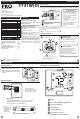
Install Instructions

Wireless Network Specications
• The thermostat will attempt to pair with the rst Base module it
“hears”. Do not attempt to create more than one “pair” at the same
time in the same place.
• To ensure paring success, place the T731W/O within a few feet of
the Base module while pairing. Once paired, the signal strength
tech menu can be used to ensure a robust wireless connection.
• Placing either device in or around large metal objects can severely
degrade the wireless range.
• The wireless network will automatically recover in the event of a
power loss or temporary signal loss.
Specications
19
Network Specications
• A single base module can support up to 7 remotes.
• If more than one thermostat is connected to a base module, the
system will control to the last interaction
• Thermostat units will require up to 60 seconds to reect changes
elsewhere in the network.
Network Capabilities
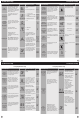
Specications
The display range of temperature ... 41˚F to 95˚F (5˚C to 35˚C)
The control range of temperature.... 44˚F to 90˚F (7˚C to 32˚C)
Load rating.................................................1 amp per terminal, 1.5 amp
maximum all terminals combined
Swing (cycle rate or dierential) ...... Heating is adjustable from 0.2˚ to 2.0˚
Cooling is adjustable from 0.2˚ to 2.0˚
Power source ...........................................18 to 30 VAC, NEC Class II, 50/60 Hz
for hardwire
Battery power from 2 AA Alkaline
batteries
Operating ambient ............................... 32˚F to +105˚F (0˚C to +41˚C)
Operating humidity .............................. 90% non-condensing maximum
Dimensions of thermostat ................. 4.7”W x 4.4”H x 1.1”D
Frequency ................................................ 916 MHz
Thermostat
Load rating ............................................... 1 amp per terminal, 1.5 amp
maximum all terminals combined.
Power source ...........................................18 to 30 VAC, NEC Class II, 50/60 Hz
Operating ambient ............................... 32˚F to +150˚F (0˚C to +65˚C)
Operating humidity .............................. 90% non-condensing maximum
Base Module
20
Changes or modications not expressly approved by the manufacturer could
void the user’s authority to operate the equipment.
Note:
Establishing A Connection
Establishing Communication between the thermostat &
the base module
The Thermostat and Base module in this package are linked at our factory.
Upon power up they will automatically begin communicating. If you wish
to make any changes to the network such as adding or removing devices,
please follow the instructions on this page.
Establishing A Connection
17
18
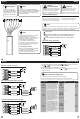
On the Base module:
1. Press the button next to the LED.
2. The Base module will begin double blinking pink for 2 minutes while it
waits
for a remote to join.
3. Once a device joins, the LED will show green blinks and return to
normal operating mode.
How To Pair
On the Thermostat:
1. Press and hold the light button for 3 seconds. The LED will ash 3 times
and pair with the base module.
2. The Thermostat will attempt to connect to a Base module within range
3. Once paired, the LCD will temporarilly display “PAIRED” when it joins with
a Base module.
How To Unpair
On the Base Module:
1. PRESS and HOLD the button next to the LED for 6 seconds.
2. The Base module LED will turn RED for 6 seconds.
3. All connected devices will be deleted.
On the Thermostat:
1. Enter the “UNPAIRING” tech menu.
2. Press and hold the “+” button.
3. The LCD will show “UNPAIRED”.
4. The Thermostat will no longer be connected to a network.
Base Module LED Information
The Base module’s LED is used to communicate the status of the wireless
network.
• Green Blink at 3s: Normal operating mode. All devices are connected
and healthy.
• Yellow Blink at 3s: Normal operating mode. One or more (but not all)
remote devices are NOT reporting.
• Red Blink at 3s: Normal operating mode. ALL network devices are
NOT reporting.
• White Blink at 3s: Unpaired mode. Base module is powered but is NOT
paired to any remotes.
• Blue double blink: Transmission received from a remote.
• Purple double blink: Base module is in pairing mode waiting for a remote.
• Green 5 quick blinks: A remote has successfully been added to the
basemodules network.
This equipment has been tested and found to comply with the limits for a Class
B digital device, pursuant to part 15 of the FCC Rules. These limits are designed
to provide reasonable protection against harmful interference in a residential
installation. This equipment generates, uses and can radiate radio frequency
energy and, if not installed and used in accordance with the instructions, may
cause harmful interference to radio communications. However, there is no
guarantee that interference will not occur in a particular installation. If this
equipment does cause harmful interference to radio or television reception,
which can be determined by turning the equipment o and on, the user is
encouraged to try to correct the interference by one or more of the following
measures:
• Reorient or relocate the receiving antenna.
• Increase the separation between the equipment and receiver.
• Connect the equipment into an outlet on a circuit dierent from that to
which the receiver is connected.
• Consult the dealer or an experienced radio/TV technician for help.
Note: