
Install Instructions
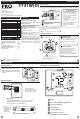

Wiring Technician Setup
11
12
Cooling
Swing
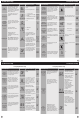
Tech Setup Steps
Adjustment Options Default
LCD Will Show
Room
Temperature
Calibration
This feature allows the installer to
change the calibration of the am-
bient room temperature display.
For example, if the thermostat
reads 70 degrees and you would
like it to read 72 then select +2.
0˚F
4 ˚ - -4 ˚
9
10
Caution:
Electrical Hazard
All components of the control
system and the thermostat
installation must conform to
Class II circuits per the NEC Code.
Warning:
Failure to disconnect the power
before beginning to install this
product can cause electrical
shock or equipment damage.
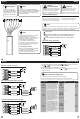
Power supply
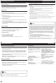
Typical 1H/1C System: 2 Speed Fan
Wiring Wiring
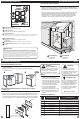
The base module is
packaged with labeled
thermostat wire. Wire
appropriately into the
PTAC board terminals.
Wiring Note:
The thermostat and Base Module
come factory linked (communicating)
out of the box. However, if the link is
lost, use the process on page 14 to
re-link the devices.
Note:
The base module may be mounted
using adhesive tape, such as
double-sided tape or hook and loop
strips. The base module must be
hardwired (C & R terminals
connected to 24V power). Use
secondary source of securement to
prevent module from dropping into
condenser drain pan.
Note:
Connecting to a PTAC:
When connecting the Base Module
to a PTAC, refer to the PTAC
manufacturer instructions to enable
remote thermostat operation.
R
Y
W
C
GL
GH
COMPRESSOR
RELAY
HEAT RELAY
FAN LOW RELAY
FAN HIGH RELAY
C
R
L2
L1
Typical 1H/1C System: 1 Speed Fan
R
Y
W
C
GL
GH
HEAT RELAY
FAN RELAY
COMPRESSOR
RELAY
Typical 1H/1C Heat Pump System: 2 Speed Fan
R
Y
W
C
GL
GH
COMPRESSOR
RELAY
FAN LOW RELAY
FAN HIGH RELAY
C
R
L2
L1
C
R
L2
L1
Typical 2H/1C Heat Pump System: 2 Speed Fan
C
R
L2
L1
COMPRESSOR
RELAY
AUX HEAT
RELAY
FAN LOW RELAY
FAN HIGH RELAY
CALIBRATE
The swing setting, often called
“cycle rate”, “dierential” or “antic-
ipation” is adjustable and dictates
how frequenlty the system cycles
on and o. For example: A swing
setting of 0.8˚ will turn the
heating on at approximately 0.8˚
below the setpoint and turn the
heating o at approximately 0.5˚
above the setpoint.
1. To enter Tech Setup Menu, press and hold and together for 3 seconds.
2. Use or to select the desired valve for each setting.
3. Tap previous or next to select dierent tech settings.
4. To exit Tech Setup Menu, press and hold and together for 3 seconds
or wait 60 seconds.
COOL CHANGE
OVER VALVE
HEAT CHANGE
OVER VALVE
O
B
COOL CHANGE
OVER VALVE
HEAT CHANGE
OVER VALVE
O
B
The swing setting, often called
“cycle rate”, “dierential” or “antic-
ipation” is adjustable and dictates
how frequenlty the system cycles
on and o. For example: A swing
setting of 0.8˚ will turn the
cooling on at approximately 0.8˚
above the setpoint and turn the
cooling o at approximately 0.8˚
below the setpoint.
0.2 ˚ - 2 ˚
0.8˚
Heating
Swing
0.2 ˚ - 2 ˚
0.8˚
R
C
B
O
GLGH
W
Y
0.8
COOL
SWING
0.8
HEAT SWING
1. Tech settings must be transferred to the basemodule.
2. The transfer happens automatically when you exit the tech menu.
Important Tech Setting Notes
The thermostat must be set to O or B to match the changeover
valve, O is the cool changeover valve, B is the heat chageover
valve.
The Aux. Heat Relay is energized as the second stage of heat.
Thermostat Wiring Tips
C Terminal
The C (common wire) terminal does
not have to be connected when the
thermostat is powered by batteries.
Wire Specications
Use shielded or non-shielded
18-22 gauge thermostat wire.
Most PTAC systems support two speed fan operation. In a single speed
fan PTAC system or conventional single speed fan system, the GL terminal
will be used and “I” must be selected in the Technician Setup Menu.
Note:
0