
Install Instructions

5
6
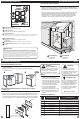
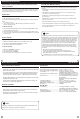
Base Module - PTAC Installation
Side Mount:
Inside PTAC
Housing
Front Mount:
Inside PTAC
Housing
Base Module Mounting Tips
Range between the thermostat and the base module is up to 100 feet
with no obstructions and up to 50 feet through standard building
materials. To optimize the range try placing the base module with no
metal between it and the thermostat.
The base module is designed to be mounted behind the front grille
of a packaged terminal air conditioner (PTAC). Refer to the PTAC
manufacturer’s manual for instruction to remove the front grille.
Check clearance to ensure the t of front grille after base module
installation. See below for a few location recommendations.
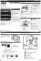
The low battery indicator is displayed when the AA battery power is low. If the user
fails to replace the battery within 21 days, the screen will only show the low battery
indicator but maintain all functionality. If the user fails to replace the batteries after
an additional 21 days (days 22-42 since rst “low battery” display) the setpoints will
change to 55˚F (Heating) and 85˚F (Cooling). If the user adjusts the setpoint away from
either of these, it will hold for 4 hours then return to either 55˚F or 85˚F. After day 63
the batteries must be replaced immediately to avoid freezing or overheating because
the thermostat will shut the unit o until the batteries are changed.
Important
Ambient Temperature:
Displays the current room temperature
Energy Ecient Globe:
Indicates you are making an energy ecient set at
temperature.
Staging Indicaators:
If these or the fan indicators are ashing, it means that the system is in a delay of some
type (compressor delay, cooling fan delay, or staging delay) or a pending change.
Set At Temperature:
Displays the selected desired room temperature.
Wireless Symbol: Indicates you have a wireless connection.
1
2
3
Next
Heat
Cool
Prev
Auto
On LHM
Set At
COOL ON
HEAT ON
FAN ON
STAGE 1+2
Next
Heat
Cool
Prev
Auto
On LHM
Set At
COOL ON
HEAT ON
FAN ON
STAGE 1+2
Thermostat Quick Reference
Low Battery Indicator: Replace batteries when this indicator
appears.
1
2
3
Base Module Mounting Tips
7
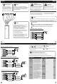
Wiring
8
When Working With A Vertical Unit
1. Do not mount Module inside the cabinet of the unit, or in a
metal enclosure.
2. Mount on the outside of the unit to maximize wireless
communication.
When Working With A Metal Sleeve Cabinet, Room Cabinet,
or PTAC Cover
1. If cabinet has open bottom, mount the module just inside the
cabinet as close to the open bottom as possible without placing it in
danger of being bumped or touched by furnishings, vaccum, etc.
2. Another good module location would be on the underside of the
top of the cabinet or cover. Directly behind the open Louver/Grill.
Front Panel
Chasis
Sleeve Cabinet
Rough-In
Wall Opening
Caution:
Electrical Hazard
All components of the
control system and the
thermostat installation must
conform to Class II circuits
per the NEC Code.
Warning:
Do not overtighten terminal
block screws, as this can
damage the terminal block.
A damaged terminal block
can keep the thermostat
from tting on the subbase
correctly or cause system
operation issues.
Installation Tip
Max Torque = 6in-lbs.
Wiring
If you are replacing a thermostat,
make note of the terminal
connections on the thermostat
that is being replaced. In some
cases the wiring connections will
not be color coded. For example,
the green wire may not be
connected to the G terminal.
Loosen the terminal block
screws. Insert wires then
retighten terminal block screws.
Place nonammable insulation
into wall opening to prevent
drafts.
1.
2.
3.
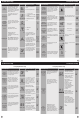
Terminal Designations
R
Failure to disconnect the power
before beginning to install this
product can cause electrical
shock or equipment damage.
C
B
O
GL
Heat Pump System
1 HEAT 1 COOL / 2 HEAT 1 COOL
Conventional System
1 HEAT 1 COOL
Transformer Power
Transformer Common
Changeover Valve
Energized in HEAT
Fan Relay, Low
Changeover Valve
Energized in COOL
Second Stage of HEAT
First Stage of HEAT and COOL
Transformer Power
Transformer Common
Fan Relay, Low
First Stage of HEAT
First Stage of COOL
N/A
N/A
GH
W
Y
Fan Relay, High Fan Relay, High