
User`s guide


1 Installation
1.1 Connecting the T-Max® Timing System
1) Place a T-Max® 3A in each room. Place the T-Max® Mgr/Pro at the
front desk.
2) A 50’ modular RJ-22 cable (phone type cable) is provided with each T-
Max® 3A. Run one modular cable from the T-Max® Mgr/Pro location to
T-Max® 3A in the nearest tanning room. Run the other modular cables
from room to room in a daisy-chain fashion. (See fig. F, page 20).
Congratulations on your purchase of the T-Max® Series Tanning System. The
T-Max® is designed for complete automation and control of your tanning
equipment. The T-max® Manager can be used as a stand alone unit or can be
controlled by a computer using many third party software packages. Manual
operation is accomplished via front panel controls.
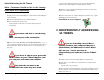
It is very important you use the cables
provided with your T-Max® timers. Making
your own cables is not recommended.
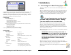
Components:
T-Max® Manager Pro:
1 T-Max® Manager Pro Unit
1 9V @ 800 mA Power Transformer
1 RS-232 Cable Com Port Adapter
1 ADNET 2000™ Utility Software (3.5” diskette)
1 T-Max® Manager User’s Manual
3)
Connect the modular cables to each T-Max® 3A and the T-Max®
Mgr/Pro. It does not matter which port you use, the top or the bottom,
because there is not an in or an out. When finished, each T-Max® 3A
should have a modular cable connected to each port, with the exception of
the last T-Max® 3A in the series.
T-Max® 3A/F (Sold separately, one required for each unit in the salon):
1 T-Max® 3A Timer Interface
1 9V @ 200mA Transformer
1 T-Max® 3A User’s Guide
1 Modular cable with RJ-22 connectors on both ends
Contact your dealer if any components are missing.
4) Connect the tanning bed to the “J3 Contact” screw terminals on the back
of the T-Max® 3A.
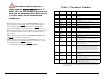
Specifications:
T-Max® ManagerPro:
IMPORTANT
: There may be many wires visible on
the tanning bed. Two of these wires are specifically
used for connecting the bed to an external timer. If
you are not sure which two wires to use, refer to
the tanning bed’s manual or contact the bed’s
manufacturer.
Power Supply IN: 120 VAC
OUT: 9 DC @ 1Amp
Current Draw 800 mA
Dimensions 12.75”x5.5”x1”
Communications Mgr-PC RS-232C, 9600 Baud, 8Bit, 1 Stop Bit, No Parity
T-Max® 3A:
Power Supply IN: 120 VAC
OUT: 9-12V (DC or AC)@800mA
Current Draw 200mA
Dimensions Cover Plate 5.25”x5.25”
5) Each T-Max® 3A came with a 9-12V power supply. If the power
supply is not already connected, connect a power supply to the “PWR IN 9-
12V” screw terminal on the back of each T-Max® 3A.
T-Max 3A PCB 2.5”x3.75”x1.5”
Relay: 220VAC @ 5A; SPST Form A
Display:
T-Max® Manager: 64 dual color lights showing bed status
6) Plug each of the T-Max® 3A’s power supplies into a standard 110V
power outlet.
1, 16x2 VFD display shows bed time/status
T-Max® 3A: 1, two digit display showing bed time & status
_____________________________________________________
T-Max® Manager/Pro and T-Max® 3A User’s Guide Page
1
T-Max® Manager/Pro and T-Max® 3A User’s Guide Page 2