_____________________________________________________ T-Max® Manager/Pro and T-Max® 3A User’s Guide Page i T-Max® Manager/Pro and T-Max® 3A User’s Guide Page ii
1 INSTALLATION ..................................................................2 1.1 CONNECTING THE T-MAX® TIMING SYSTEM ....................2 AUTO ADDRESSING THE 3A TIMERS............................................3 2 6.4 CONNECTING A REMOTE PUSH BUTTON TO THE T-MAX® 3A (OPTIONAL) .........................................................................18 6.5 T-MAX® ENCLOSURE (OPTIONAL) .................................18 INDEPENDENTLY ADDRESSING 3A TIMERS ............4 2.
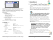
1 Installation 1.1 Connecting the T-Max® Timing System 1) Place a T-Max® 3A in each room. Place the T-Max® Mgr/Pro at the front desk. 2) A 50’ modular RJ-22 cable (phone type cable) is provided with each TCongratulations on your purchase of the T-Max® Series Tanning System. The T-Max® is designed for complete automation and control of your tanning equipment. The T-max® Manager can be used as a stand alone unit or can be controlled by a computer using many third party software packages.
Auto Addressing the 3A Timers. As you press the Start/Stop buttons in each room, the Maximum Bed Number on the T-Max® Mgr/Pro will automatically count up. Note: Customers should not be in the tanning beds while auto addressing. 11) When you have finished with addressing the timers, press the Enter button on the T-Max® Mgr/Pro. 7) Apply power to the T-Max® Mgr/Pro. Wait until the T-Max® Mgr/Pro 12) After a short pause, the T-Max® Manager/Pro will then scan. Lights is done scanning.
4) Press and hold the Start/Stop and Up buttons together, simultaneously, 2) Press and hold the Start/Stop and Up buttons simultaneously on the T- concurrently, and at the same time, on the T-Max® 3A until a”.1” appears on the display. This should take about 5-6 seconds. Release the buttons. Max® 3A until a .1 appears on the display. This should take 5-6 seconds. Release the buttons. 5) Press the Start/Stop button on the display. A flashing number will appear.
3 SETTING UP THE MANAGER/PRO WITHOUT A COMPUTER. If you want the session to start right away, enter a delay of 0. The maximum setting for delay is 10 minutes. This setting is for every bed in the salon. 7) The following message will appear: MGR START MODE. Enter the desired Auto Start Mode followed by the ENTER button. 3.1 Description The T-Max® Mgr/Pro has 64 dual-colored lights showing bed status. A 16x2 VFD display on the upper right corner of the T- Max® Mgr/Pro shows bed status and times.
This number must be equal to or higher than the highest address that a TMax® 3A is set. For example if you have six beds, but are addressing the T-Max® 3As to 1,2,3,4,5, and 8, set the maximum bed number to 8. 9) The following message will appear: MANAGER NUM. If you are using one Manager, press ENTER. If you are using multiple Managers, enter the T-Max® Mgr/Pro address, followed by the ENTER button. Up to 8 T-Max® Mgr/Pro’s can be connected in a single salon. One TMax® Mgr/Pro must be set to address 0.
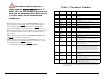
3.2.3 Security Levels 3.2.2 What are Parameters Parameters are values stored in each T-Max® 3As such as Lamp Hours, Session Counts, etc. Table 1 shows the parameter numbers and details about them. To get or change parameters, do the following: 1) Press the BED NUMBER you want to check or change, followed by the ENTER key. The bed number and its status will appear. 2) Press the CALL/MENU button. 3) The following message will appear: SECURITY#.
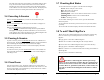
The delay will count down on the display. If an Infinite delay has been set up, the session time will show but will not count down. DELAY will show for status. Once the customer presses the Start/Stop button on the T-Max® 3A in the room, the session will start. The display will show the session time counting down and the status will stay ON. 3.4 Canceling A Session 3.7 Checking Bed Status To check the status of a bed, glance at the 64 dual colored lights. Green = Bed is ready for a new session.
4 IN-ROOM SINGLE BED CONTROL 4.1 Starting a Session If you are using a T-Max® Mgr/Pro and you want to use the T-Max® 3As manually, you must unplug power from the T-Max® Mgr/Pro, unplug power from all the T-Max® 3A’s, then plug the timers back in. Power must stay removed from the T-Max® Mgr/Pro while the T-Max® 3A is being used independently. 1) Press the Up and Down button on the T-Max® 3A until the session time is displayed.
6 OTHER FEATURES and OPTIONS 6.1 Cool Down Mode Cool Down mode is used for beds that require a time to cool down before the next session can be run. High-pressure beds primarily require this. While the T-Max® 3A is in Cool Down Mode, a session cannot be started until the cool down time has expired. To enable Cool Down Mode, set parameter 13 to the time in minutes you want the cool down time to last. Setting parameter 13 to 0 disables Cool Down Mode.
T-Max® 3A. Connect the grommets to hold the wires in tight. Plug any unused holes with the provided plastic plugs. Connect the T-Max® 3A to the T-Max® Enclosure using the four screws provided with the T-Max® 3A. 6.6 ADNET Opto-Isolator (Optional) 7 FIGURES 7.1 Figure A - Front View Of The T-Max® 3A The ADNET Opto-Isolator® is a device that isolates both sides of the communications between the T-Max® Manager and the rest of the salon.
7.3 Figure E - The T-Max® Mgr/Pro 7.5 Figure H - Modular Cable Pin-outs RJ-22 Connector Untwisted Modular Cable RJ-22 Connector Front View of the T-Max® Mgr/Pro 7.4 Figure F - Connecting The T-Max® Series RJ-22 Connector Untwisted Modular Cable RJ-22 Connector Use this diagram if you are making your own cables Important!!! Salon Systems, Inc. highly recommends that you do not modify the cables provided with each T-Max® 3A. If you need longer cables, contact your dealer or Salon Systems, Inc.
8 TROUBLE SHOOTING The T-Max® Series has been designed for years of trouble free service. However, if a problem does arise, please follow these trouble shooting steps before calling technical support. 1) No Lights Illuminated on the T-Max® Mgr/Pro. Make sure that the transformer is plugged into the wall and into the power input on the T-Max® Mgr/Pro. Try plugging the T-Max® Mgr/Pro into a different outlet.
10) I can start sessions from the Master T-Max® Mgr/Pro, but not the Slave T-Max® Mgr/Pro. Enter Security Level 1 (See your enclosed Security Sheet). An Asterisk (*) will be displayed on the lower left corner of the T-Max® Mgr/Pro. Cycle power to both the Slave T-Max® Mgr/Pro then the Master T-Max® Mgr/Pro. Watch the VFD display. On the lower right, make sure the display shows “VER-202/T”.
ADNET-Repeater™, 21 Auto Addressing See Quick Installation. Auto Start Manual Setup, 7 Bed Status, 13 Cable Pinouts See Modular Cable Pinouts.