INSTRUCTIONS FOR USE Pro-Ject SIGNATURE
Pro-Ject SIGNATURE Your contribution to environmental protection Disposal of packaging material: The packaging protects the device against damage during transport. Packaging materials have been selected with environmental aspects and possibilities of their liquidation and they are recyclable. Disposal of old device: Old devices must be collected separately in order to optimise the recovery and recycling of the materials they contain and reduce the impact on human health and the environment.
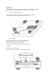
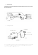
Set-up Read thoroughly the manual and follow all instructions after unpacking the turntable. Make the turntable assembly of distributed components in the package. 1. Installation of adjustable feet (9) The feet are disassembled for transport and stored in the package of platter. Screw the feet into the thread inserts of the turntable plinth. 2. Platter assembly Before platter (1) assembly, unscrew three transport screws. Remove protective covers from shaft and platter bearing.
3. Idler pulley assembly Idler pulley consists of two parts. One is powered by the motor units and one is floated on the magnetic cushion. Both parts form a whole stored on a common shaft. Before installing this kit remove the covers from the shaft and bearing. Check for adequate lubrication. If necessary, lubricate with grease in the attached accessories. 4.
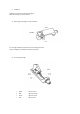
. Headshell Headshell is stored in a separated packaging. When assembling, follow instructions: a) Mounting the cartridge into the headshell: For cartridge assembly use fasteners from cartridge accessories. Fix the cartridge in the middle of headshell oval holes.
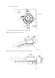
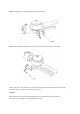
c) Headshell assembly Plug headshell into the front of the tube. Connector pin must be oriented into the groove. Fixing nut tighten on the tonearm tube properly. d) Counterweight assembly Put on counterweight on the support rod. Tighten the locking screw gradually and watch than the shaft entry into thread groove. Then tighten the locking screw. Correction of counterweight’s weight is provided by additional counterweight is also tighten by the set screw.
Setting range of counterweight: 1. Counterweight without additional counterweight This setting balance cartridge with weight 4.5 – 8 gr. 2. Counterweight with additional counterweight with dimensions Ø15mm, length 30mm. This setting balance cartridge with weight 8 – 15 gr. 3. Counterweight with additional counterweight with dimensions Ø15mm, length 45mm. This setting balance cartridge with weight 15 – 23 gr. Please note that the maximum visible part of this additional counterweight is 21mm.
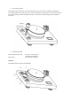
e) Assembly of removable tonearm part to the turntable Detachable tonearm part, which we already prepared, carefully put to it’s place. Insert output connector carefully into socket in housing. Positioning pin must be directed to cartridge counterweight. After insertion the connector into socket, lock the connector with fixing nut. f) Tonearm output connection Attached signal cabel plug to tonearm 5-PIN connector, which is located on the bottom side of the turntable. Keep the right positioning.
g) Anti-skating assembly Assembly of anti-skating is described in the following four steps: Step 1: Mounting the thread on the hook screw Step 2: Put the thread on the correct position in the tonearm groove
Step 3: Mounting the anti-skating sliding mechanism on the shaft Step 4: Positioning of the sliding mechanism. Eye of the thread insert on the pin in the groove. When the tonearm is over the first outer groove of the record, the anti-skating thread must be already tensioned, when it’s in the end, it must be still on tension. WARNING: When the thread isn’t tensioned at the beginning, at the end already falling on the other side. Be careful, there is a danger to rip off thread by tensile force.
OPERATING AND CALIBRATION 1. Cartridge setting Effective length = 304.8mm (12”) (distance between needle of the cartridge and the vertical rotation axis of the tonearm) Mounting distance= 291.6mm (distance between spindle and the vertical rotation axis of the tonearm) Outer nullpoint: r= 62,5mm For correct setting use the protractor or Pro-Ject Align It tool.
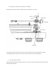
Setting the position of cartridge in the headshell: For setting the correct position of cartridge in headshell grooves we designed for you small tool from transparent plexiglass. Please note that this tool is only for headshell from Pro-Ject SIGNATURE tonearm. Step 1: Place the tool with groove to the headshell as shown. Step 2: Then move the cartridge to the correct position. Correct position is, if the top of the needle is in the same plane like as comparative plane of tool.
2. Setting the vertical tracking force (VTF) Place counterweight halfway along the counterweight support rod, being sure to have the locking screw uppermost. With the power of and platter static, place the stylus pressure gauge onto the platter. To set the required VTF place the tip of the stylus on the pressure gauge. Moving the counterweight towards the cartridge will reduce VTF and away will increase VTF.
For adjustment and control of vertical tracking force (VTF) is supplied in the package electronic stylus balance Pro-Ject Meaure IT II Product information: Case made of aluminium 4 digit LCD-Display with backlight Capacity 0-5g Variance ± 0,002g Auto calibration function Auto off after 60 seconds Batteries supplied (teo AAA cells) Dimensions (W x H x D) 122 x 25 x 55mm Weight 170g 3. Adjusting the vertical tracking angle (VTA) Put a record on the platter.
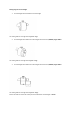
4. Adjusting the azimuth The cartridge needle must be vertical in the record groove in order to trace the groove wall modulations correctly. A small azimuth adjusting screw on the headshell allows incorrect azimuth to be corrected. Correct position can be checked from the front view, preferably with needle placed on a mirror which is placed on platter. Examples of incorrect azimuth setup: Too much left angle: Too much right angle: The correct position is 100% perpendicular to the record.
5. Mounting distance adjustment Loosen the locking nut allows the linear shifting of the tonearm. Adjust correct distance by using of the scale. The correct mounting distance 304.8 mm on the scale is valid only if the cartridge is in the correct position on the headshell. However there are exist very special and different cartridge types which makes a correct mounting distance impossible. In this case you can change the distance of the arm easily and allow you to use all available cartridge types.
6. Anti-skating force adjustment With the anti-skating slider adjust the position of the arm weight at 45 degrees. Downforce: Lower than 13mN 13 - 18 mN 18 - 25mN Anti-skating groove: st 1 from bearing rings nd 2 from bearing rings rd 3 from bearing ring 7. Adjusting the turntable plane Put the spirit level on the top of the turntable. With feet that are screw-type balance the turntable. Control the plane in several directions.
8. Connect the turntable to the power supply and amplifier Turntable is supplied with a power supply suitable for your country’s mains supply. Check the label before connecting to ensure compliance with the mains rating in your house. Connect the low voltage plug from the power supply to the socket on the rear of the turntable before connecting the power supply to the mains. Signal cabel connect with your phono preamplifier Red – right channel White – left channel 9.
Turntable control is performed by the touch screen. After turning the switch on, the display shows logo Pro-Ject. Touching the screen you can control the turntable functions. Touching on field 33 or 45 select the desired speed. The display shows „WAIT“ . After reaching rated speed is displayed selected value 33,3 or 45,1 . Rated speed can be correct by touching the + or –, which changes the value by 0.1 % Turn off or pause the recording perform is done by touching the STOP.
Time and date setting By touching the screen on the „T“ go to time and date setting window. Touch the mark with altered number and correct value by + or -. The set values can be saved by touching the „S“. To return to control touch the „C“. Turntable accessories: 1. 2. 3. 4. 5. 6. 7. 8. 9. 10. 11. 12. 13. 14. 15. 16. 2 pieces of anti-skating thread Centering ring Allen key 1.
Potential incorrect use and fault conditions PRO-JECT turntables are manufactured to the highest standards and undergo strict quality controls before leaving the factory. Faults that may possibly occur are not necessarily due to material or production faults but can sometimes be caused by incorrect use or unfortunate circumstances. Therefore the following list of common fault symptoms is included. The platter doesn’t turn although the unit is switched on: The unit is not connected to the mains power supply.
Technical specifications Pro-Ject SIGNATURE Nominal speeds Switching speeds Speed variance Wow and flutter Signal to noise Drive Motor Platter Power supply Power consumption Dimensions Weight 33,3/45,11 r.p.