
Specifications


107 www.zylogic.com.cn
S
S
i
i
d
d
e
e
b
b
a
a
n
n
d
d
S
S
i
i
g
g
n
n
a
a
l
l
T
T
i
i
m
m
i
i
n
n
g
g
C
C
h
h
a
a
r
r
a
a
c
c
t
t
e
e
r
r
i
i
s
s
t
t
i
i
c
c
s
s
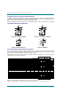
The sideband signals are controls to and from the embedded 8032 "Turbo" microcontroller, unique to the
Zylogic ZE5 family. Each signal is associated with a specific dedicated resource inside the 8032 micro-
controller.
The values below indicate the number of Bus Clock cycles required for the signal to be recognized by the
microcontroller.
S
S
i
i
d
d
e
e
b
b
a
a
n
n
d
d
S
S
i
i
g
g
n
n
a
a
l
l
F
F
u
u
n
n
c
c
t
t
i
i
o
o
n
n
a
a
l
l
D
D
i
i
a
a
g
g
r
r
a
a
m
m
XTAL
Timer 0
RXDOUT
TXD
RXDIN
INT1
INT0
HPINT
T0
T1
T2
T2EX
CPU ResetRSTC
Timer 1
Timer 2
Interrupt
Controller
UART
Reset
Crystal Osc.
Figure 65. Embedded 8032 "Turbo" microcontroller sideband signals.
S
S
i
i
d
d
e
e
b
b
a
a
n
n
d
d
S
S
i
i
g
g
n
n
a
a
l
l
T
T
i
i
m
m
i
i
n
n
g
g
C
C
h
h
a
a
r
r
a
a
c
c
t
t
e
e
r
r
i
i
s
s
t
t
i
i
c
c
G
G
u
u
i
i
d
d
e
e
l
l
i
i
n
n
e
e
s
s
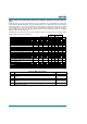
Final Final
Speed Grade -25 -40
Description Symbol Fig. Device Min Max Min Max
Units
Timer 0
T0 pulse width T
ST0P
19 All 5 5 T
BCYC
Timer 1
T1 pulse width T
ST1P
19 All 5 5 T
BCYC
Timer 2
T2 pulse width T
ST2P
19 All 5 5 T
BCYC
T2EX pulse width T
ST2XP
19 All 5 5 T
BCYC
Interrupts
HPINT pulse width T
SHPP
19 All 5 5 T
BCYC
INT0 pulse width T
SIT0P
19 All 5 5 T
BCYC
INT1 pulse width T
SIT1P
19 All 5 5 T
BCYC
Resets
Reset input to 8032, RSTC pulse
width
T
SRSTC
19 All 2 2 T
BCYC
Final Final