www.proform.com Model No. PFTL11716.0 Serial No. Write the serial number in the space above for reference. Serial Number Decal ACTIVATE YOUR WARRANTY To register your product and activate your warranty today, go to www.proformservice.com/ registration. CUSTOMER CARE For service at any time, go to www.proformservice.com. Or call 1-888-533-1333 Mon.–Fri. 6 a.m.–6 p.m. MT Sat. 8 a.m.–12 p.m. MT Please do not contact the store.
TABLE OF CONTENTS WARNING DECAL PLACEMENT . . . . . . . . . . . . . . . . . . . . . . . . . . . . . . . . . . . . . . . . . . . . . . . . . . . . . . . . . . . . . . . 2 IMPORTANT PRECAUTIONS . . . . . . . . . . . . . . . . . . . . . . . . . . . . . . . . . . . . . . . . . . . . . . . . . . . . . . . . . . . . . . . . . . 3 BEFORE YOU BEGIN. . . . . . . . . . . . . . . . . . . . . . . . . . . . . . . . . . . . . . . . . . . . . . . . . . . . . . . . . . . . . . . . . . . . . . . .
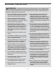
IMPORTANT PRECAUTIONS WARNING: To reduce the risk of burns, fire, electric shock, or injury to persons, read all important precautions and instructions in this manual and all warnings on your treadmill before using your treadmill. ICON assumes no responsibility for personal injury or property damage sustained by or through the use of this product. 1. It is the responsibility of the owner to ensure that all users of this treadmill are adequately informed of all warnings and precautions. 12.
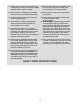
19. Always stand on the foot rails when starting or stopping the walking belt. Always hold the handrails while using the treadmill. 26. When folding or moving the treadmill, make sure that the storage latch is holding the frame securely in the storage position. 20. When a person is walking on the treadmill, the noise level of the treadmill will increase. 27. Never insert any object into any opening on the treadmill. 21. Keep fingers, hair, and clothing away from the moving walking belt. 28.
STANDARD SERVICE PLANS all 6
BEFORE YOU BEGIN Thank you for selecting the revolutionary PROFORM® POWER 1295I treadmill. The POWER 1295I treadmill offers an impressive selection of features designed to make your workouts at home more effective and enjoyable. And when you’re not exercising, the unique treadmill can be folded up, requiring less than half the floor space of other treadmills. reading this manual, please see the front cover of this manual.
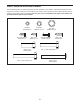
PART IDENTIFICATION CHART Use the drawings below to identify small parts used for assembly. The number in parentheses below each drawing is the key number of the part, from the PART LIST near the end of this manual. The number following the key number is the quantity used for assembly. Note: If a part is not in the hardware kit, check to see whether it is pre-attached. Extra parts may be included.
ASSEMBLY • To hire an authorized service technician to assemble the treadmill, call 1-800-445-2480 • Left parts are marked “L” or “Left” and right parts are marked “R” or “Right.” • Assembly requires two persons. • To identify small parts, see page 8. • Place all parts in a cleared area and remove the packing materials. Do not dispose of the packing materials until you finish all assembly steps.
2. Make sure that the power cord is unplugged. 2 Remove the tie securing the Upright Wire (81) to the front of the Base (94). 81 A Next, identify the Right Upright (90). Have a second person hold the Right Upright near the Base (94). 81 90 See the inset drawing. Tie the wire tie (A) in the Right Upright (90) securely around the end of the Upright Wire (81). Then, insert the Upright Wire into the lower end of the Right Upright as you pull the other end of the wire tie through the Right Upright.
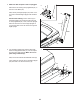
4. Hold the Right Upright (90) against the Base (94). Make sure not to pinch the Upright Wire (81). 4 Attach the Right Upright (90) and a Wheel (97) with two 3/8" x 2 1/4" Screws (7), a 3/8" x 1 1/4" Screw (63), a 3/8" x 1 3/4" Screw (62), and four 3/8" Star Washers (13) as shown; do not fully tighten the Screws yet. 7 Attach the Left Upright (not shown) in the same way. Note: There are no wires on the left side. 13 81 94 62 13 13 90 63 97 5.
6. Hold the Right Handrail (87) near the Right Upright (90). Insert the Upright Wire (81) through the hole in the bottom of the Right Handrail as shown, and then remove the wire tie (A) from the Upright Wire. 6 28 11 86 28 Next, attach the Right Handrail (87) to the Right Upright (90) with two 5/16" x 2 1/2" Screws (28) and two 5/16" Star Washers (11). Make sure not to pinch the Upright Wire (81). Firmly tighten the Screws.
8. Set the console assembly (F) face down on a soft surface to avoid scratching the console assembly. Remove and save the four 5/16" x 1/2" Screws (4). 8 4 F 4 9. Set the console assembly (F) on the Left and Right Handrails (86, 87). Make sure not to pinch any wires (G, 81). 9 F Attach the console assembly (F) with the four 5/16" x 1/2" Screws (4) that you removed in step 8 and four 5/16" Star Washers (11); do not fully tighten the Screws yet.
10. Attach the console assembly (F) to the Left and Right Handrails (86, 87) with four #10 x 3/4" Screws (9) and four #10 Star Washers (5) as shown; start all four Screws, and then tighten them. 10 F 9 5 9 86 5 87 11. See the inset drawing. Connect the Upright Wire (81) to the console wire (G). The connectors should slide together easily and snap into place. If they do not, turn one connector and try again.
12. Attach the Right Handrail Cover (92) to the Right Handrail (87) with three #8 x 1/2" Screws (1); do not overtighten the Screws. 12 Attach the Left Handrail Cover (79) to the Left Handrail (86) in the same way. 79 86 92 87 1 1 13. Slide the Left Bottom Handrail Cover (85) up against the Left Handrail Cover (79), and attach the Left Bottom Handrail Cover with two #8 x 1/2" Screws (1); do not overtighten the Screws. 13 79 Attach the Right Bottom Handrail Cover (84) in the same way.
14. Note: If the treadmill is assembled on a smooth surface, it may roll forward during this step. 14 Raise the Frame (56) to the upright position. IMPORTANT: Do not raise the Frame past the vertical position. Have a second person hold the Frame until step 16 is completed. I I 11 Remove the two 5/16" x 3/4" Screws (25) from the Latch Crossbar (38). 25 Orient the Latch Crossbar (38) as shown. Make sure that the “This side toward belt” sticker (H) is facing the treadmill.
16. Remove the 5/16" Nut (12) and the 5/16" x 2 1/4" Bolt (3) from the bracket on the Latch Crossbar (38). 16 12 38 3 Align the upper end of the Storage Latch (53) with the bracket on the Latch Crossbar (38), and insert the 5/16" x 2 1/4" Bolt (3) through the bracket and the Storage Latch. This will push a spacer (K) out of the Storage Latch; discard the spacer. K 56 53 Next, tighten the 5/16" Nut (12) onto the 5/16" x 2 1/4" Bolt (3).
. Press the two tabs on the Tablet Holder (110) into the slots (L) in the console assembly (F). 18 110 Attach the Tablet Holder (110) to the console assembly (F) with four #8 x 5/8" Machine Screws (115). Note: Start the two top Machine Screws first, and then start the two bottom Machine Screws. Be careful not to overtighten the Machine Screws. Start First L F 115 IMPORTANT: The Tablet Holder (110) is designed for use with most full-size tablets.
HOW TO USE THE TREADMILL HOW TO CONNECT THE POWER CORD more amps. To avoid overloading the circuit, do not plug other electrical devices, except for lowpower devices such as cell phone chargers, into the surge suppressor or into an outlet on the same circuit. IMPORTANT: If the treadmill is connected to an AFCI-equipped outlet and your circuit breaker trips repeatedly when the treadmill is used, see the front cover of this manual to purchase an arc filter.
CONSOLE DIAGRAM MAKE YOUR FITNESS GOALS A REALITY WITH IFIT.COM FEATURES OF THE CONSOLE The advanced treadmill console offers a selection of features designed to make your workouts more effective and enjoyable. With your new iFit-enabled fitness equipment, you can use an array of features on iFit.com to make your fitness goals a reality: When you use the manual mode, you can change the speed and incline of the treadmill with the touch of a button.
HOW TO TURN ON THE POWER HOW TO USE THE TOUCH SCREEN IMPORTANT: If the treadmill has been exposed to cold temperatures, allow it to warm to room temperature before you turn on the power. If you do not do this, you may damage the console displays or other electrical components. The console features a tablet with a full-color touch screen. The following information will help you become familiar with the tablet’s advanced technology: Plug in the power cord (see page 19).
HOW TO SET UP THE CONSOLE To use the sound system, see page 28. To use the internet browser, see page 28. To use the equipment settings mode, see page 29. To use the maintenance mode, see page 30. To use the wireless network mode, see page 31. To use the tablet holder, see page 32. Before using the treadmill for the first time, set up the console. 1. Connect to your wireless network.
If you press one of the numbered speed buttons, the walking belt will gradually change speed until it reaches the selected speed setting. As you walk or run on the treadmill, the screen can show the following workout information: • The incline level of the treadmill To select a speed setting that includes a decimal— such as 3.5 mph—press two numbered buttons in succession. For example, to select a speed setting of 3.5 mph, press the 3 button and then immediately press the 5 button.
6. Measure your heart rate if desired. When you are finished using the treadmill, press the power switch into the off position and unplug the power cord. IMPORTANT: If you do not do this, the treadmill’s electrical components may wear prematurely. Note: If you use the handgrip heart rate monitor and the chest heart rate monitor at the same time, the console will not display your heart rate accurately. For information about the chest heart rate monitor, see page 28.
At the end of the first segment of the workout, the treadmill will automatically adjust to the speed and/ or incline settings for the next segment. 5. Measure your heart rate if desired. The workout will continue in this way until the last segment ends. The walking belt will then slow to a stop and a workout summary will appear on the screen. After you view the workout summary, touch the Finish button to return to the main menu.
HOW TO USE A PULSE WORKOUT 4. Start the workout. Touch the Start button to start the workout. A moment after you touch the button, the walking belt will begin to move. Hold the handrails and begin walking. Pulse workouts automatically control the speed and incline of the treadmill to keep your heart rate near a target level while you exercise. Note: You must wear a chest heart rate monitor to use a pulse workout. The workout will function in the same way as the manual mode (see page 22). 1.
6. Monitor your progress with the displays. To compete in a race that you have previously scheduled, touch the Compete button. To view your Workout History, touch the Track button. To use a set-a-goal workout, touch the Set A Goal button (see page 25). See step 5 on page 23. 7. Turn on the fan if desired. See step 7 on page 24. To switch users within the account, touch the user button near the lower right corner of the screen. 8. When you are finished exercising, remove the key from the console.
8. Turn on the fan if desired. HOW TO USE THE SOUND SYSTEM See step 7 on page 24. To play music or audio books through the console sound system while you exercise, plug a 3.5 mm male to 3.5 mm male audio cable (not included) into the jack on the console and into a jack on your personal audio player; make sure that the audio cable is fully plugged in. Note: To purchase an audio cable, see your local electronics store. 9. When you are finished exercising, remove the key from the console.
HOW TO USE THE EQUIPMENT SETTINGS MODE IMPORTANT: You must still unplug the power cord after using the treadmill. Set the update time for a time when you normally use the treadmill and will be available to unplug the power cord after an update. 1. Select the settings main menu. Insert the key into the console (see HOW TO TURN ON THE POWER on page 21). Next, select the main menu (see step 2 on page 22). Then, touch the gears button near the lower right corner of the screen to select the settings main menu.
11. Enable or disable a passcode. HOW TO USE THE MAINTENANCE MODE The console features a child-safety passcode, designed to prevent unauthorized users from using the treadmill. 1. Select the settings main menu. Touch the Passcode button. To enable a passcode, touch the Enable checkbox. Then, enter a 4-digit passcode of your choice. Touch Save to use this passcode. Touch Cancel to return to the equipment settings mode and not use a passcode. To disable the passcode, touch the Disable checkbox. 2.
HOW TO USE THE WIRELESS NETWORK MODE 4. Calibrate the incline system of the treadmill. The console features a wireless network mode that allows you to set up a wireless network connection. Touch the Calibrate Incline button. Then, touch the Begin button to calibrate the incline system. The treadmill will automatically rise to the maximum incline level, lower to the minimum incline level, and then return to the starting position. This will calibrate the incline system.
When a list of networks appears, touch the desired network. Note: You will need to know your network name (SSID). If your network has a password, you will also need to know the password. HOW TO USE THE TABLET HOLDER IMPORTANT: The tablet holder is designed for use with most full-size tablets. Do not place any other electronic device or object in the tablet holder. An information box will ask if you want to connect to the wireless network.
HOW TO FOLD AND MOVE THE TREADMILL HOW TO FOLD THE TREADMILL HOW TO MOVE THE TREADMILL To avoid damaging the treadmill, adjust the incline to zero before you fold the treadmill. Then, remove the key and unplug the power cord. CAUTION: You must be able to safely lift 45 lbs. (20 kg) to raise, lower, or move the treadmill. Before moving the treadmill, fold it as described at the left. CAUTION: Make sure that the storage latch is locked in the storage position. Moving the treadmill may require two people.
MAINTENANCE AND TROUBLESHOOTING MAINTENANCE SYMPTOM: The power turns off during use Regular maintenance is important for optimal performance and to reduce wear. Inspect and properly tighten all parts each time the treadmill is used. a. Check the power switch (see drawing c at the left). If the switch has tripped, wait for five minutes and then press the switch back in. Regularly clean the treadmill and keep the walking belt clean and dry.
c. Your treadmill features a walking belt coated with high-performance lubricant. IMPORTANT: Never apply silicone spray or other substances to the walking belt or the walking platform unless instructed to do so by an authorized service representative. Such substances may deteriorate the walking belt and cause excessive wear. If you suspect that the walking belt needs more lubricant, see the front cover of this manual. SYMPTOM: The treadmill will not connect to the wireless network a.
b. If the walking belt slips when walked on, first remove the key and UNPLUG THE POWER CORD. Using the hex key, turn both idler roller screws clockwise, 1/4 of a turn. When the walking belt is correctly tightened, you should be able to lift each edge of the walking belt 2 to 3 in. (5 to 7 cm) off the walking platform. Be careful to keep the walking belt centered. Then, plug in the power cord, insert the key, and walk on the treadmill for a few minutes. Repeat until the walking belt is properly tightened.
EXERCISE GUIDELINES Burning Fat—To burn fat effectively, you must exercise at a low intensity level for a sustained period of time. During the first few minutes of exercise, your body uses carbohydrate calories for energy. Only after the first few minutes of exercise does your body begin to use stored fat calories for energy. If your goal is to burn fat, adjust the intensity of your exercise until your heart rate is near the lowest number in your training zone.
PART LIST Key No. Qty. 1 2 3 4 5 6 7 8 9 10 11 12 13 14 15 16 17 18 19 20 21 22 23 24 25 26 27 28 29 30 31 32 33 34 35 36 37 38 39 40 41 42 43 44 45 46 47 48 49 50 42 41 1 4 4 5 4 2 4 2 16 6 8 12 3 1 2 1 4 2 2 2 1 8 6 2 1 4 1 4 1 2 6 5 4 1 1 1 4 2 2 1 1 1 1 2 1 4 1 2 Model No. PFTL11716.0 R1116A Description Key No. Qty.
Key No. Qty. 101 102 103 104 105 106 107 108 109 1 5 1 1 1 1 2 6 2 Description Key No. Qty.
15 40 2 2 103 59 30 12 6 61 44 2 116 104 35 39 2 14 26 57 43 24 15 39 35 2 14 112 2 2 60 108 25 11 23 6 45 108 114 42 24 47 46 59 30 12 30 12 102 35 39 14 2 26 19 108 59 6 12 14 108 21 100 50 113 35 3 39 2 14 114 49 25 11 55 53 108 107 56 38 105 34 19 48 6 46 108 20 12 50 6 21 100 54 59 30 12 15 102 34 107 EXPLODED DRAWING A Model No. PFTL11716.
EXPLODED DRAWING B Model No. PFTL11716.
EXPLODED DRAWING C Model No. PFTL11716.
EXPLODED DRAWING D Model No. PFTL11716.
ORDERING REPLACEMENT PARTS To order replacement parts, please see the front cover of this manual.