Model No. PFEVEL87914.0 Serial No. Write the serial number in the space above for reference. USER’S MANUAL Serial Number Decal CUSTOMER SERVICE UNITED KINGDOM Call: 08457 089 009 From Ireland: 053 92 36102 Website: www.iconsupport.eu E-mail: csuk@iconeurope.com Write: ICON Health & Fitness, Ltd. c/o HI Group PLC Express Way CASTLEFORD WF10 5QJ UNITED KINGDOM AUSTRALIA Call: 1800 993 770 E-mail: australiacc@iconfitness.
TABLE OF CONTENTS WARNING DECAL PLACEMENT . . . . . . . . . . . . . . . . . . . . . . . . . . . . . . . . . . . . . . . . . . . . . . . . . . . . . . . . . . . . . . .2 IMPORTANT PRECAUTIONS. . . . . . . . . . . . . . . . . . . . . . . . . . . . . . . . . . . . . . . . . . . . . . . . . . . . . . . . . . . . . . . . . . 3 BEFORE YOU BEGIN. . . . . . . . . . . . . . . . . . . . . . . . . . . . . . . . . . . . . . . . . . . . . . . . . . . . . . . . . . . . . . . . . . . . . . . .4 ASSEMBLY . . . . . . . . .
IMPORTANT PRECAUTIONS WARNING: To reduce the risk of serious injury, read all important precautions and instructions in this manual and all warnings on your elliptical before using your elliptical. ICON assumes no responsibility for personal injury or property damage sustained by or through the use of this product. 1. It is the responsibility of the owner to ensure that all users of the elliptical are adequately informed of all precautions. able to safely support 85 lbs. (38.
BEFORE YOU BEGIN Thank you for selecting the revolutionary PROFORM® 900 ZLE elliptical. The 900 ZLE elliptical provides an impressive selection of features designed to make your workouts at home more effective and enjoyable. manual. To help us assist you, note the product model number and serial number before contacting us. The model number and the location of the serial number decal are shown on the front cover of this manual. For your benefit, read this manual carefully before you use the elliptical.
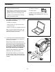
ASSEMBLY • Assembly requires two persons. one Phillips screwdriver • Place all parts in a cleared area and remove the packing materials. Do not dispose of the packing materials until you finish all assembly steps. one rubber mallet Assembly may be easier if you have a set of wrenches. To avoid damaging parts, do not use power tools. • In addition to the included tool(s), assembly requires the following tool(s): 1. G o to www.iconsupport.eu on your computer and register your product.
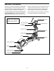
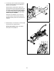
3. If necessary, remove and discard the shipping supports and the shipping screws attached to the front of the Frame (1). 3 84 73 With the help of another person, place some packing inserts from the packing material under the Frame (1) so that the Frame is lifted off the floor. Have another person hold the elliptical to prevent it from moving from side to side until this step is completed. Attach the Front Stabilizer (73) to the Frame (1) with two M10 x 120mm Screws (84).
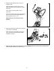
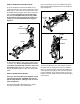
5. Rotate the Right Upper Body Arm (9) to the upright position. 5 Attach the Right Upper Body Arm (9) to the Right Upper Body Leg (6) with an M10 x 50mm Screw (95). Then, tighten the indicated M10 x 45mm Screw (78). 9 20 78 Press the Upper Body Arm Cover (20) downward and turn it so that it is flush with the Right Leg Front and Rear Covers (11, 15). Repeat this step on the other side of the elliptical. 95 6. Plug the Power Adapter (104) into the receptacle on the frame of the elliptical.
HOW TO USE THE ELLIPTICAL HOW TO PLUG IN THE POWER ADAPTER HOW TO MOVE THE ELLIPTICAL IMPORTANT: If the elliptical has been exposed to cold temperatures, allow it to warm to room temperature before you plug in the power adapter. If you do not do this, you may damage the console displays or other electronic components. Due to the size and weight of the elliptical, moving it requires two persons.
HOW TO EXERCISE ON THE ELLIPTICAL Then, lift the handle on the front stabilizer and tip the frame upright until the elliptical rests on the small and large storage feet. To mount the elliptical, hold the handlebars or the upper body arms and step onto the pedal that is in the lower position. Then, step onto the other pedal. Push the pedals until they begin to move with a continuous motion. Note: The pedals can turn in either direction.
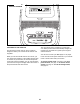
CONSOLE DIAGRAM FEATURES OF THE CONSOLE The console also offers a selection of preset workouts. Each preset workout automatically changes the resistance of the pedals as it guides you through an effective workout. The advanced console offers an array of features designed to make your workouts more effective and enjoyable. When you use the manual mode of the console, you can change the resistance of the pedals with the touch of a button.
HOW TO USE THE MANUAL MODE 4. Follow your progress with the display. 1. Turn on the console. The left display—This display can show the elapsed time and the approximate number of calories you have burned. The display will change modes every few seconds. Press any button or begin pedaling to turn on the console. When you turn on the console, the display will turn on. A tone will sound and the console will be ready for use.
rate will be shown. For the most accurate heart rate reading, hold the contacts for at least 15 seconds. 5. Measure your heart rate if desired. You can measure your heart rate using either the handgrip heart rate monitor or an optional chest heart rate monitor (see page 14 for information about the optional chest heart rate monitor). If your heart rate is not shown, make sure that your hands are positioned as described. Be careful not to move your hands excessively or to squeeze the contacts tightly.
HOW TO USE A PRESET WORKOUT The resistance level for the next segment will appear in the center display for a few seconds to alert you. The resistance of the pedals will then change. 1. Turn on the console. Press any button or begin pedaling to turn on the console. The target speed for the next segment will appear in the right display for a few seconds to alert you. 2. Select a preset workout. As you exercise, keep your pedaling speed near the target speed for the current segment.
HOW TO USE THE SOUND SYSTEM The console has three backlight options. The ON option keeps the backlight on while the console is on. The AUTO option keeps the backlight on only while you are pedaling. The OFF option turns the backlight off. To play music or audio books through the console sound system while you exercise, plug a 3.5 mm male to 3.
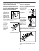
MAINTENANCE AND TROUBLESHOOTING MAINTENANCE Next, look into the access opening and locate the Reed Switch (58). Rotate the Pulley (66) until a Magnet (41) is aligned with the Reed Switch. Note: For clarity, the shields are shown removed in the drawing below. Inspect and tighten all parts of the elliptical regularly. Replace any worn parts immediately. To clean the elliptical, use a damp cloth and a small amount of mild soap.
HOW TO ADJUST THE DRIVE BELT See EXPLODED DRAWING C on page 23. Remove all of the M4 x 16mm Screws (61) and M4 x 38mm Screws (64) from the Left and Right Shields (44, 45). Make sure to note which size Screws come from which holes. Then, carefully remove the Left Shield. If the pedals slip while you are pedaling, even while the resistance is adjusted to the highest setting, the drive belt may need to be adjusted. To adjust the drive belt, first unplug the power adapter. Loosen the Idler Screw (97).
EXERCISE GUIDELINES Burning Fat—To burn fat effectively, you must exercise at a low intensity level for a sustained period of time. During the first few minutes of exercise, your body uses carbohydrate calories for energy. Only after the first few minutes of exercise does your body begin to use stored fat calories for energy. If your goal is to burn fat, adjust the intensity of your exercise until your heart rate is near the lowest number in your training zone.
SUGGESTED STRETCHES The correct form for several basic stretches is shown at the right. Move slowly as you stretch; never bounce. 1. Toe Touch Stretch Stand with your knees bent slightly and slowly bend forward from your hips. Allow your back and shoulders to relax as you reach down toward your toes as far as possible. Hold for 15 counts, then relax. Repeat 3 times. Stretches: Hamstrings, back of knees and back. 1 2. Hamstring Stretch Sit with one leg extended.
PART LIST Key No. Qty. 1 2 3 4 5 6 7 8 9 10 11 12 13 14 15 16 17 18 19 20 21 22 23 24 25 26 27 28 29 30 31 32 33 34 35 36 37 38 39 40 41 42 43 44 45 46 47 1 1 1 1 1 1 1 1 1 2 1 1 1 1 1 1 4 1 1 2 1 1 4 1 2 2 1 1 4 2 2 1 8 1 1 2 1 2 1 1 2 1 2 1 1 1 2 Model No. PFEVEL87914.0 R0114A Description Key No. Qty.
Key No. Qty. 95 96 97 98 99 100 101 2 1 1 1 6 1 1 Description Key No. Qty. M10 x 50mm Screw Pivot Screw Idler Screw M6 Washer M8 Locknut Power Wire Left Upper Body Leg 102 103 104 105 106 * * 1 4 1 1 1 – – Description Upright Axle M8 x 20mm Bolt Power Adapter Receiver Extension Wire User’s Manual Assembly Tool Note: Specifications are subject to change without notice. For information about ordering replacement parts, see the back cover of this manual. *These parts are not illustrated.
43 74 25 53 84 60 71 79 66 21 41 61 70 99 99 51 103 82 68 96 97 41 103 24 98 38 50 77 72 47 61 99 46 4 57 48 56 52 61 94 54 71 40 79 38 58 99 61 61 82 60 25 1 7 65 93 43 100 55 74 42 102 105 104 83 61 28 59 106 55 69 73 65 87 85 61 59 83 3 61 91 80 2 63 84 88 62 67 61 48 5 61 86 90 61 21 89 16 EXPLODED DRAWING A Model No. PFEVEL87914.
81 12 14 8 10 22 29 92 101 19 33 18 39 29 20 30 81 75 95 9 13 75 20 32 33 49 23 76 31 61 15 17 61 10 23 33 61 76 6 78 17 22 76 33 11 EXPLODED DRAWING B Model No. PFEVEL87914.
26 61 61 61 27 64 61 36 64 44 64 61 61 61 37 64 45 65 64 65 34 64 65 65 36 61 65 61 26 65 35 65 EXPLODED DRAWING C Model No. PFEVEL87914.
ORDERING REPLACEMENT PARTS To order replacement parts, see the front cover of this manual.