
User`s manual
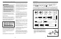

6 15
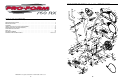
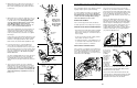
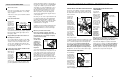
2. Whilst another person lifts the back of the Frame (1),
attach the Rear Stabiliser (9) to the Frame with two
M10 x 75mm Carriage Bolts (34) and two M10 Nylon
Locknuts (33).
34
9
1
3
2
43
44
1
73
79
59
Adjustment
Holes
Make sure the
Wire Harnesses
(44, 79) do not
get pinched and
damaged during
this step.
44
67
67
59
3. Whilst another person holds the Upright (2) in the posi-
tion shown, connect the Extension Wire Harness (44)
to the Wire Harness (79). Carefully pull the upper
end of the Extension Wire Harness to remove any
slack. Whilst holding the upper end of the
Extension Wire Harness, insert the Upright into the
Frame (1). Do not pinch the Wire Harnesses.
Next, turn the Upright Knob (43) counterclockwise sev-
eral turns. Pull the Knob, slide the Upright (2) down
until the Knob is aligned with one of the four adjust-
ment holes, and then release the Knob. Do not tighten
the Knob yet.
Feed the upper end of the Extension Wire Harness (44)
through the Upright Extension (73). Attach the Upright
Extension to the Upright (2) with three M10 x 27mm
Button Screws (67) and three M10 Split Washers (59).
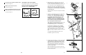
4. Connect the wire harness on the Handgrip Pulse
Sensor (29) to the indicated wire harness on the
Console (23). Insert both wire harnesses into the open-
ing in the bottom of the Console. Next, insert the metal
tube on the Handgrip Pulse Sensor into the opening in
the bottom of the Console. Be careful not to pinch
the wire harnesses.
See the inset drawing. Align the holes in the bracket on
the Console (23) with the holes in the metal tube on
the Handgrip Pulse Sensor (29). Tighten two M4 x
16mm Screws (52) through the bracket into the tube as
shown.
29
23
Wire Harnesses
4
2
33
33
Tube
52
23
Bracket
29
52
Tube
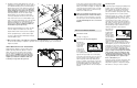
5. The Console (23) requires four 1.5V “D” batteries;
alkaline batteries are recommended. Press the tab on
the battery cover, and lift off the battery cover. Insert
four batteries into the battery compartment. Make sure
that the batteries are oriented as shown by the dia-
gram inside the battery compartment. Reattach the
battery cover.
23
Tab
Batteries
Battery
Cover
5
Inspect and tighten all parts of the elliptical crosstrainer
regularly. Replace any worn parts immediately.
To clean the elliptical crosstrainer, use a damp cloth
and a small amount of mild detergent. Important:
Keep liquids away from the console and keep the
console out of direct sunlight. During storage,
remove the batteries from the console.
BATTERY REPLACEMENT
If the console display becomes dim, the batteries
should be replaced. See assembly step 5 on page 6.
HANDGRIP PULSE SENSOR TROUBLESHOOTING
• Avoid moving your hands whilst using the handgrip
pulse sensor; excessive movement may interfere
with heart rate readings. Do not hold the metal con-
tacts too tightly.
• For the most accurate heart rate reading, hold the
metal contacts for about 15 seconds.
• For optimal performance of the handgrip pulse sen-
sor, clean the metal contacts with a soft cloth—do
not use alcohol, abrasives, or chemicals.
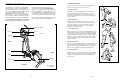
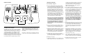
HOW TO ADJUST THE REED SWITCH
If the console does not display correct feedback, the
reed switch should be adjusted. To do this, you must
remove the Pedal Springs (11), the right Pedal Disc
(15), and the Side Shields (3, 4). See step 9 on page
8 and remove the Pedal Springs.
Next, remove the four Screws (51) from the right
Pedal Disc (15), and slide the Pedal Disc off. Remove
all Screws (52, 64) from the Right Side Shield (4) and
the two Screws (77) from beneath the Pedal Disc, and
remove the Right Side Shield. Remove all Screws
(52) from the Left Side Shield (3) and remove the Left
Side Shield.
Next, see the drawing below and locate the Reed
Switch (53). Loosen, but do not remove, the indicated
M4 x 16mm Screw (52). Slide the Reed Switch slightly
toward or away from the Magnet (58) on the flywheel.
Retighten the Screw. Turn the left Pedal Disc (15) for a
moment. Repeat until the console displays correct
feedback. When the Reed Switch is correctly adjusted,
reattach the Side Shields (3, 4), the right Pedal Disc
(15), and the Pedal Springs (11).
HOW TO ADJUST THE DRIVE BELT
If you can feel
the pedals slip
whilst you are
pedalling,
even when the
resistance is
adjusted to
the highest
level, the
Drive Belt (19)
may need to
be adjusted.
To adjust the
Drive Belt, you must first remove both side shields.
See HOW TO ADJUST THE REED SWITCH at the
left and remove the side shields.
Next, loosen the M8 x 22mm Flat Head Screw (68)
and turn the M10 x 70mm Bolt (62) until the Drive Belt
(19) is tight. When the Drive Belt is tight, tighten the
Flat Head Screw. Reattach the side shields.
MAINTENANCE AND TROUBLESHOOTING
64
77
51
51
77
52
52
64
64
11
11
4
15
3
58
53
52
15
68
62
19