www.proform.com Model No. PFEL94910.0 Serial No. Write the serial number in the space above for reference. Serial Number Decal QUESTIONS? If you have questions, or if parts are damaged or missing, DO NOT CONTACT THE STORE; please contact Customer Care. IMPORTANT: Please register this product (see the limited warranty on the back cover of this manual) before contacting Customer Care. 1-888-533-1333 CALL TOLL-FREE: Mon.–Fri., 6 a.m.–6 p.m. MT Sat. 8 a.m.–4 p.m. MT ON THE WEB: www.proformservice.
TABLE OF CONTENTS WARNING DECAL PLACEMENT . . . . . . . . . . . . . . . . . . . . . . . . . . . . . . . . . . . . . . . . . . . . . . . . . . . . . . . . . . . . . .2 IMPORTANT PRECAUTIONS . . . . . . . . . . . . . . . . . . . . . . . . . . . . . . . . . . . . . . . . . . . . . . . . . . . . . . . . . . . . . . . .3 BEFORE YOU BEGIN . . . . . . . . . . . . . . . . . . . . . . . . . . . . . . . . . . . . . . . . . . . . . . . . . . . . . . . . . . . . . . . . . . . . . .4 ASSEMBLY . . . . . . . . . . . . .
IMPORTANT PRECAUTIONS WARNING: To reduce the risk of serious injury, read all important precautions and instructions in this manual and all warnings on your elliptical before using your elliptical. ICON assumes no responsibility for personal injury or property damage sustained by or through the use of this product. 1. Before beginning any exercise program, consult your physician. This is especially important for persons over age 35 or persons with pre-existing health problems. 8.
BEFORE YOU BEGIN Thank you for selecting the new PROFORM® STRIDE TRAINER 595 elliptical. The STRIDE TRAINER 595 elliptical provides a selection of features designed to make your workouts at home more effective and enjoyable. reading this manual, please see the front cover of this manual. To help us assist you, note the product model number and serial number before contacting us. The model number and the location of the serial number decal are shown on the front cover of this manual.
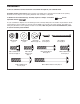
ASSEMBLY To hire an authorized service technician to assemble the elliptical, call 1-800-445-2480. Assembly requires two persons. Place all parts of the elliptical in a cleared area and remove the packing materials. Do not dispose of the packing materials until assembly is completed. In addition to the included tool(s), assembly requires a Phillips screwdriver adjustable wrench . and an As you assemble the elliptical, use the drawings below to identify small parts.
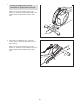
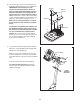
1. 1 To make assembly easier, read the information on page 5 before you begin. While a second person lifts the rear of the Frame (1), attach the Rear Stabilizer (70) to the Frame with two M10 x 85mm Patch Screws (82). 70 1 82 2. Orient the Front Stabilizer (73) so that the “Front” sticker is facing away from the front of the Frame (1). 2 82 While a second person lifts the front of the Frame (1), attach the Front Stabilizer (73) to the Frame with two M10 x 85mm Patch Screws (82).
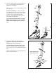
3. Orient the Upright (2) and the Top Shield Cover (37) as shown. Slide the Top Shield Cover upward onto the Upright. 3 Have a second person hold the Upright (2) near the Frame (1). Wire Tie See the inset drawing. Locate the wire tie in the Upright (2). Tie the lower end of the wire tie to the Wire Harness (42). Next, pull the upper end of the wire tie upward until the Wire Harness is routed through the Upright. Then, untie and discard the wire tie.
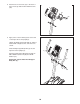
5. See the upper drawing. To avoid pinching or damaging the Pulse Wires (28) while you assemble the Handlebar (39), perform the following actions: 5 Insert the end of the left Pulse Wire (28) inside the left side of the Handlebar (39). 39 Then, insert the end of the right Pulse Wire (28) inside the right side of the Handlebar (39). See the lower drawing. Have a second person hold the Handlebar (39) in place around the Upright (2). 28 Tip: Avoid pinching the wires.
6. The Console (4) can use four D batteries (not included); alkaline batteries are recommended. IMPORTANT: If the Console has been exposed to cold temperatures, allow it to warm to room temperature before inserting batteries. Otherwise, you may damage the console displays or other electronic components. Remove the screws, remove the battery covers, insert the batteries into the battery compartments, and reattach the battery covers.
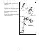
8. Attach the Console Cover (32) to the back of the Console (4) with two M4 x 48mm Screws (89). 8 4 32 89 9. Apply some of the included grease to the axle on the right side of the Upright (2). Identify the Right Upper Body Arm (9), which is marked with a “Right” sticker, and orient it as shown. 9 Slide the Right Upper Body Arm (9) onto the right side of the Upright (2). 8 Attach the Right Upper Body Arm (9) with an M8 x 20mm Patch Screw (80) and an M8 Washer (33).
10. Identify the Right Link Arm (98), which is marked with a “Right” sticker, and orient it as shown. 10 Apply some of the included grease to the axle on the Right Link Arm (98). 80 Slide a Link Arm Cover (103) onto the axle on the Right Link Arm (98). Make sure that the flat side of the Link Arm Cover is facing the Right Link Arm. Insert the Right Link Arm (98) through the Right Pedal Arm (49). Attach the Right Link Arm with an M8 x 20mm Patch Screw (80) and an M8 Washer (33).
. With the help of a second person, insert the Right Upper Body Arm (9) into the right Upper Body Leg (6). 12 Attach the Right Upper Body Arm (9) with two M8 x 45mm Button Bolts (76) and two M8 Jam Nuts (77). Make sure that the Jam Nuts are in the hexagonal holes. 8 Attach the Left Upper Body Arm (8) to the other Upper Body Leg (6) in the same way. 76 Make sure that the M8 x 45mm Button Bolts (76) are in the locations shown. Hexagonal Holes 9 6 6 77 13. See the inset drawing.
14. Attach the Rear Upright Cover (3) to the Upright (2) with three M4 x 16mm Screws (92). Orient the Front Upright Cover (16) so that the indicated arrow is pointing upward. 14 92 Press the Front Upright Cover (16) into the Rear Upright Cover (3). Press the Water Bottle Holder (5) into the Rear Upright Cover (3). Attach the Right Pedal (13) to the Right Pedal Arm (49) with three M10 x 48mm Patch Screws (75) and three M10 Split Washers (78).
16. Press the Rear Shield Cover (59) onto the Left and Right Shields (44, 45). 16 59 44 45 17. Make sure that all parts of the elliptical are properly tightened. Note: Some hardware may be left over after assembly is completed. To protect the floor or carpet from damage, place a mat under the elliptical.
HOW TO USE THE ELLIPTICAL HOW TO MOVE THE ELLIPTICAL HOW TO CHANGE THE INCLINE OF THE RAMP Due to the size and weight of the elliptical, moving it requires two persons. Stand in front of the elliptical, hold the upright, and place one foot against one of the front wheels. Pull on the upright and have a second person lift the handle until the elliptical will roll on the wheels. Carefully move the elliptical to the desired location, and then lower it to the floor.
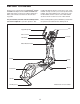
HOW TO EXERCISE ON THE ELLIPTICAL Upper Body Arms To mount the elliptical, hold the handlebars or the upper body arms and step onto the pedal that is in the lowest position. Then, step onto the other pedal. Push the pedals until they begin to move with a continuous motion. Note: The pedal discs can turn in either direction. It is recommended that you move the pedal discs in the direction shown by the arrow; however, for variety, you can turn the pedal discs in the opposite direction.
CONSOLE DIAGRAM FEATURES OF THE CONSOLE The console also offers six target toning workouts designed to work specific areas of the body. Each target toning workout has a recommended ramp incline level and will automatically change the resistance of the pedals while guiding you through an effective workout. The advanced console offers an array of features designed to make your workouts more effective and enjoyable.
HOW TO USE THE MANUAL MODE 4. Follow your progress with the display. 1. Turn on the console. The left display–This display can show the elapsed time and the approximate number of calories you have burned. The display will change modes every few seconds. Press any button or begin pedaling to turn on the console. When you turn on the console, the display will light. A tone will sound and the console will be ready for use. 2. Select the manual mode.
5. Measure your heart rate if desired. HOW TO USE A PRESET WORKOUT If there are sheets of plastic on the Contacts metal contacts on the handgrip pulse sensor, remove the plastic. In addition, make sure that your hands are clean. To measure your heart rate, hold the handgrip pulse sensor with your palms resting against the metal contacts. Avoid moving your hands or gripping the contacts tightly. 1. Turn on the console. See step 1 on page 18. 2. Select a preset workout.
During the workout, the workout profile will show your progress (see the drawing on page 19). The flashing segment of the profile represents the current segment of the workout. The height of the flashing segment indicates the resistance level for the current segment. To restart the workout, simply resume pedaling. The workout will continue until the last segment of the profile flashes and the last segment of the workout ends.
3. Adjust the ramp to the recommended incline level. HOW TO USE A TARGET TONING WORKOUT 1. Turn on the console. See HOW TO CHANGE THE INCLINE OF THE RAMP on page 15 and move the ramp to the recommended incline level for the selected target toning workout. See step 1 on page 18. 2. Select a target toning workout. To select a target toning workout, press the Workouts increase or decrease button repeatedly until the number of the desired workout appears in the right display.
HOW TO USE THE SOUND SYSTEM If you stop pedaling for several seconds, a series of tones will sound and the workout will pause. To play music or audio books through the console sound system while you exercise, plug the audio cable into the jack on the console and into the jack on your MP3 player or CD player; make sure that the audio cable is fully plugged in. To restart the workout, simply resume pedaling.
MAINTENANCE AND TROUBLESHOOTING Inspect and tighten all parts of the elliptical regularly. Replace any worn parts immediately. To clean the elliptical, use a damp cloth and a small amount of mild soap. IMPORTANT: To avoid damage to the console, keep liquids away from the console and keep the console out of direct sunlight. CONSOLE TROUBLESHOOTING If the console displays become dim, replace all the batteries at the same time; most console problems are the result of low batteries.
HOW TO ADJUST THE REED SWITCH Locate the Reed Switch (58). Loosen, but do not remove, the M4 x 16mm Screw (92). If the console does not display correct feedback, the reed switch should be adjusted. To adjust the reed switch, you must remove the right disc cover and the right pedal disc. Using a flat screwdriver, remove the right Disc Cover (18). 27 92 81 58 18 41 24 Next, rotate the Crank Assembly (24) until a Magnet (41) is aligned with the Reed Switch (58).
EXERCISE GUIDELINES WARNING: Burning Fat—To burn fat effectively, you must exercise at a low intensity level for a sustained period of time. During the first few minutes of exercise, your body uses carbohydrate calories for energy. Only after the first few minutes of exercise does your body begin to use stored fat calories for energy. If your goal is to burn fat, adjust the intensity of your exercise until your heart rate is near the lowest number in your training zone.
SUGGESTED STRETCHES The correct form for several basic stretches is shown at the right. Move slowly as you stretch—never bounce. 1 1. Toe Touch Stretch Stand with your knees bent slightly and slowly bend forward from your hips. Allow your back and shoulders to relax as you reach down toward your toes as far as possible. Hold for 15 counts, then relax. Repeat 3 times. Stretches: Hamstrings, back of knees, and back. 2 2. Hamstring Stretch Sit with one leg extended.
NOTES 27
PART LIST—Model No. PFEL94910.0 Key No. Qty. 1 2 3 4 5 6 7 8 9 10 11 12 13 14 15 16 17 18 19 20 21 22 23 24 25 26 27 28 29 30 31 32 33 34 35 36 37 38 39 40 41 42 43 44 45 46 47 48 49 50 1 1 1 1 1 2 1 1 1 2 2 1 1 1 2 1 8 2 2 1 1 2 1 1 1 1 1 2 4 2 1 1 8 1 1 1 1 2 1 1 2 1 7 1 1 1 2 2 1 2 Description Key No. Qty.
Key No. Qty. 101 102 103 104 105 106 107 108 109 110 2 2 2 2 4 2 2 1 1 1 Description Key No. Qty. 111 112 113 114 115 * * * * Link Arm Bushing Bushing Cover Link Arm Cover Link Arm Screw Cover Bushing Set Ramp Axle Bushing Latch Spring Latch Latch Spacer Latch Pin 1 1 2 1 7 – – – – Description Spring Bracket Latch Screw M10 Washer Latch Snap Ring M5 x 16mm Screw Userʼs Manual Assembly Tool Grease Packet Wire Tie Note: Specifications are subject to change without notice.
85 33 30 29 15 22 80 8 84 12 17 33 29 11 84 17 19 78 99 75 33 103 78 85 104 10 6 14 78 17 17 79 3 29 78 78 100 79 96 92 77 5 33 80 97 102 101 76 95 29 97 37 78 85 33 49 78 15 17 92 84 30 13 92 33 96 80 79 79 2 4 75 78 28 79 78 39 93 100 17 103 84 77 79 79 98 6 19 32 17 102 76 89 17 33 101 9 16 85 104 33 10 80 22 11 EXPLODED DRAWING A—Model No. PFEL94910.
18 26 18 41 92 46 92 41 92 31 47 92 48 70 92 82 24 91 44 43 79 113 50 51 91 115 47 92 48 59 57 40 58 92 90 52 34 56 7 87 43 91 86 83 36 54 71 35 91 77 55 91 38 115 7166 88 115 38 43 72 115 92 63 65 74 53 69 94 73 82 77 64 42 63 79 60 92 27 92 92 92 109 110 21 74 107 111 105 112 113 92 68 67 108 61 43 62 1 25 50 105 114 106 107 31 106 92 92 45 81 92 20 92 92 23 EXPLODED DRAWING B—Model No. PFEL94910.
ORDERING REPLACEMENT PARTS To order replacement parts, please see the front cover of this manual.