proform.com Model No. PFBE01220.0 Serial No. Write the serial number in the space above for reference. Serial Number Decal (under seat) REGISTER YOUR PRODUCT To register your product and activate your warranty today, go to my.proform.com. CUSTOMER CARE For service at any time, go to support.proform.com. Or call 1-888-533-1333 Mon.–Fri. 6 a.m.–6 p.m. MT Sat. 8 a.m.–12 p.m. MT Please do not contact the store. CAUTION Read all precautions and instructions in this manual before using this equipment.
TABLE OF CONTENTS WARNING DECAL PLACEMENT . . . . . . . . . . . . . . . . . . . . . . . . . . . . . . . . . . . . . . . . . . . . . . . . . . . . . . . . . . . . . . .2 IMPORTANT PRECAUTIONS . . . . . . . . . . . . . . . . . . . . . . . . . . . . . . . . . . . . . . . . . . . . . . . . . . . . . . . . . . . . . . . . . . 3 BEFORE YOU BEGIN. . . . . . . . . . . . . . . . . . . . . . . . . . . . . . . . . . . . . . . . . . . . . . . . . . . . . . . . . . . . . . . . . . . . . . . .
IMPORTANT PRECAUTIONS WARNING: To reduce the risk of serious injury, read all important precautions and instructions in this manual and all warnings on your weight bench before using your weight bench. ICON assumes no responsibility for personal injury or property damage sustained by or through the use of this product. bench to mount, dismount, and use the weight bench. To protect the floor or carpet from damage, place a mat under the weight bench. 1.
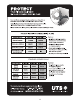
STANDARD SERVICE PLANS 4
BEFORE YOU BEGIN Thank you for selecting the versatile PROFORM® SPORT INCLINE/DECLINE BENCH XT weight bench. The weight bench is designed to help develop the major muscle groups of the upper body. Whether your goal is to tone your body, build dramatic muscle size and strength, or improve your cardiovascular system, the weight bench will help you to achieve the specific results you want. reading this manual, please see the front cover of this manual.
PART IDENTIFICATION CHART See the drawings below to identify small parts used in assembly. The number in parentheses by each drawing is the key number of the part, from the PART LIST near the end of this manual. IMPORTANT: If you cannot find a part in the hardware kit, check to see if it has been preassembled. To avoid damaging parts, do not use power tools for assembly.
ASSEMBLY 1. To use the assembly steps in this manual, first see the helpful tips below. • To hire an authorized service technician to assemble this product, call 1-800-445-2480. • In addition to the included tool(s), assembly requires the following tools: • Assembly requires two persons. two adjustable wrenches • Place all parts in a cleared area and remove the packing materials. Do not dispose of the packing materials until you finish all assembly steps.
3. Attach the Front Leg (2) to the Frame (1) with two M10 x 63mm Bolts (16), two M10 Large Washers (27), and two M10 Locknuts (19); do not tighten the Locknuts yet. 3 27 16 19 1 27 2 4. Orient a Stabilizer (4) so that the widest sides (A) of the 50mm Outer Caps (12) touch the floor. 4 19 Attach the Stabilizer (4) to the Rear Leg (3) with two M10 x 65mm Carriage Bolts (18) and two M10 Locknuts (19); do not tighten the Locknuts yet.
6. Insert a Pad Tube (10) into the Front Leg (2). Next, slide a Foam Pad (9) onto each end of the Pad Tube. Then, press two Pad Caps (11) into the Pad Tube. 6 11 9 Repeat this step with the other Pad Tube (not shown), Foam Pads (9), and Pad Caps (11). 10 2 9 11 9 9 11 11 7. Attach the Pivot Bracket (6) to the Backrest Frame (5) with two M10 x 70mm Bolts (26) and two M10 Locknuts (19); do not tighten the Locknuts yet.
8. Using a plastic bag to keep your fingers clean, apply some of the included grease to an M10 x 85mm Bolt (23). 8 5 Insert the Pivot Bracket (6) into the slot in the Frame (1). Attach the Backrest Frame (5) to the Frame with the M10 x 85mm Bolt (23) and an M10 Locknut (19). Do not overtighten the Locknut; the Backrest Frame must pivot easily. 19 1 Then, attach an M10 x 20mm Bolt (25) and an M10 Locknut (19) to the hole in the end of the Pivot Bracket (6). 23 Grease 19 See step 7.
10. Orient the Backrest (7) as shown, and attach it to the Backrest Frame (5) with four M6 x 16mm Screws (24); start all the Screws, and then tighten them. To avoid damaging the Backrest, tighten the Screws only until the Backrest does not move or feel loose. 10 7 24 5 24 11. Orient the Seat (8) as shown, and attach it to the Frame (1) with four M6 x 65mm Screws (17) and four M6 Washers (22); start all the Screws, and then tighten them.
ADJUSTMENT This section explains how to adjust the weight bench. See the EXERCISE GUIDELINES on page 13 for important exercise information, and refer to the accompanying exercise guide to see the correct form for several exercises. Make sure that all parts are properly tightened each time the weight bench is used. Replace any worn parts immediately. The weight bench can be cleaned with a damp cloth and a mild, non-abrasive detergent; do not use solvents.
EXERCISE GUIDELINES FOUR TYPES OF STRENGTH WORKOUTS to determine the appropriate length of time for each workout, and the numbers of repetitions and sets to complete. Progress at your own pace and be sensitive to your body’s signals. Follow each workout with at least one day of rest. Note: A “repetition” is one complete cycle of an exercise, such as one sit-up. A “set” is a series of repetitions.
PART LIST Key No. Qty. 1 2 3 4 5 6 7 8 9 10 11 12 13 14 15 16 1 1 1 2 1 1 1 1 4 2 4 4 4 1 1 2 Model No. PFBE01220.0 R1220A Description Key No. Qty.
EXPLODED DRAWING Model No. PFBE01220.
ORDERING REPLACEMENT PARTS To order replacement parts, please see the front cover of this manual.