
Operation Manual

8
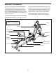
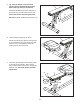
3. Tip: It may be helpful to have a second
person raise and hold the Rear Frame (18)
while you do this step.
Orient the Rear Stabilizer (3) as indicated by the
sticker; make sure that the welded tubes are
on the side shown.
Attach the Rear Stabilizer (3) to the Rear Frame
(18) with two M10 x 100mm Screws (13).
13
3
3
18
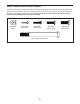
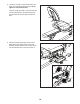
4. See the inset drawing. Pull the Foot Plate Knob
(49), lower the Foot Plate (68), and then release
the Foot Plate Knob.
Orient the Rail (5) so that the adjustment holes
are closer to the front of the dual trainer.
Next, orient the Rail Collar (6) as shown, and
slide it onto the front of the Rail (5).
Then, slide the Rail Collar (6) and the Rail (5)
onto the Rail Pivot Bracket (96).
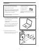
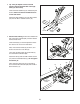
Attach the Rail (5) with four M8 x 20mm Screws
(15) and the Small Rail Plate (7); do not tighten
the Screws yet.
Next, attach the Rail Cover (6) to the Rail (5)
and to the Rail Pivot Bracket (96) with two M6 x
20mm Screws (14).
5
15
Adjustment
Holes
14
6
96
7
4
14
Welded
Tube
49
68