
Operation Manual
6
S
G
S
JN
SS
GR
GR
JN
Nb
S7'
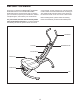
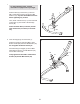
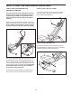
''>//%-0'%'K%1"'WGX'/4'/0"'L#%*"'WSX'V$/0'64)#'
Eb'['SO**'K)//42'!-#"V1'WGRX'%2U'64)#'Eb'
.%10"#1'WJNX7'Tip: Start all the Button Screws
before tightening any of them.
''F0"2;'%//%-0'%'L#%*"'L44/'WSSX'/4'/0"')2U"#1$U"'
46'/0"'L#%*"'WSX'V$/0'%2'EN'['Sa**'L&%2<"'
!-#"V'WNbX7
Attach the other Base (not shown) and the
other Frame Foot (not shown) in the same
way.
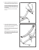
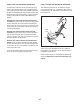
G7' 821"#/'/0"'I3#$<0/'WNX'$2/4'/0"'L#%*"'WSX7
'''>//%-0'/0"'I3#$<0/'WNX'V$/0'/0#""'Eb'['SO**'
K)//42'!-#"V1'WGRX'%2U'/0#""'Eb'.%10"#1'WJNX7'
Do not tighten the Button Screws yet.
'L$2$10'%//%-0$2<'/0"'I3#$<0/'WNX'V$/0'%2'Eb'['
OO**'K)//42'K4&/'WN_X;'/V4'Eb'.%10"#1'WJNX;'
%2U'%2'Eb'C4-T2)/'WNaX7
' Firmly tighten the three M8 x 15mm Button
Screws (29) and the M8 Locknut (46).
To make assembly easier, read the
information on page 5 before you begin.
G
N
S
GR
JN
JN
N_
JN
JN
Na