Model No. PETL10810.0 Serial No. Write the serial number in the space above for reference. USERʼS MANUAL Serial Number Decal QUESTIONS? If you have questions, or if there are missing parts, please contact us: UK Call: 08457 089 009 From Ireland: 053 92 36102 Website: www.iconsupport.eu E-mail: csuk@iconeurope.com Write: ICON Health & Fitness, Ltd. c/o HI Group PLC Express Way Whitwood, West Yorkshire WF10 5QJ UK AUSTRALIA Call: 1-800-237-173 E-mail: australiacc@iconfitness.
TABLE OF CONTENTS WARNING DECAL PLACEMENT . . . . . . . . . . . . . . . . . . . . . . . . . . . . . . . . . . . . . . . . . . . . . . . . . . . . . . . . . . . . . .2 IMPORTANT PRECAUTIONS . . . . . . . . . . . . . . . . . . . . . . . . . . . . . . . . . . . . . . . . . . . . . . . . . . . . . . . . . . . . . . . .3 BEFORE YOU BEGIN . . . . . . . . . . . . . . . . . . . . . . . . . . . . . . . . . . . . . . . . . . . . . . . . . . . . . . . . . . . . . . . . . . . . . .5 ASSEMBLY . . . . . . . . . . . . .
IMPORTANT PRECAUTIONS WARNING: To reduce the risk of serious injury, read all important precautions and instructions in this manual and all warnings on your treadmill before using your treadmill. ICON assumes no responsibility for personal injury or property damage sustained by or through the use of this product. 1. Before beginning any exercise program, consult your physician. This is especially important for persons over age 35 or persons with pre-existing health problems. 11.
23. Inspect and properly tighten all parts of the treadmill regularly. 19. Never leave the treadmill unattended while it is running. Always remove the key, unplug the power cord, and press the power switch into the off position when the treadmill is not in use. (See the drawing on page 5 for the location of the power switch.) 24. 20. Do not attempt to raise, lower, or move the treadmill until it is properly assembled. (See ASSEMBLY on page 6, and HOW TO FOLD AND MOVE THE TREADMILL on page 24.
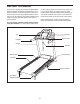
BEFORE YOU BEGIN Thank you for selecting the revolutionary PROFORM® 900 ZLT treadmill. The 900 ZLT treadmill offers an impressive selection of features designed to make your workouts at home more enjoyable and effective. And when youʼre not exercising, the unique treadmill can be folded up, requiring less than half the floor space of other treadmills. ing this manual, please see the front cover of this manual.
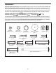
ASSEMBLY Assembly requires two persons. Set the treadmill in a cleared area and remove all packing materials. Do not dispose of the packing materials until assembly is completed. Note: The underside of the treadmill walking belt is coated with high-performance lubricant. During shipping, some lubricant may be transferred to the top of the walking belt or the shipping carton. This is normal and does not affect treadmill performance.
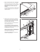
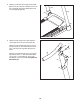
1. Make sure that the power cord is unplugged. 1 Remove the 3/8" Nut (10), the 3/8" x 2" Bolt (8), and the shipping bracket (A) from the Base (95). Repeat this step on the other side of the treadmill. The 3/8" Nuts (10) and the 3/8" x 2" Bolts (8) will be used in assembly steps 3 and 6. Discard the shipping brackets. 95 8 10 2. With the help of a second person, carefully tip the treadmill onto its left side.
3. Attach a Wheel (96) to the Base (95) with the 3/8" x 2" Bolt (8) and the 3/8" Nut (10) that you removed in step 1. Do not overtighten the Nut; the Wheel must turn freely. 3 Press a Base Cap (89) into the Base (95). 89 8 96 10 4. Identify the Right Upright (85), which is marked with a “Right” sticker. Hold the Right Upright near the Base (95) as shown. 4 See the inset drawing. Tie the wire tie in the Right Upright (85) securely around the end of the Upright Wire (87).
6. With the help of a second person, carefully tip the treadmill onto its right side. Partially fold the Frame (55) so that the treadmill is more stable; do not fully fold the Frame yet. 6 C B Remove and discard the two indicated bolts (B) and the shipping bracket (C). Attach a Wheel (96) to the Base (95) with the 3/8" x 2" Bolt (8) and the 3/8" Nut (10) that you removed in step 1. Do not overtighten the Nut; the Wheel must turn freely. 89 8 Press a Base Cap (89) into the Base (95). 95 7.
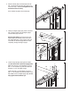
8. Identify the Left Base Cover (88) and the Right Base Cover (91). Slide the Left Base Cover onto the Left Upright (84) and the Right Base Cover onto the Right Upright (85). 8 84 85 88 91 9. Identify the Left Upright Cover (80). Slide the Left Upright Cover onto the Left Upright (84). Identify the Left Handrail (82). Remove the tie from the bracket on the Left Handrail. If necessary, press the 5/16" Cage Nut (38) back into place.
10. Slide the Right Upright Cover (86) onto the Right Upright (85). Remove the tie from the bracket on the Right Handrail (83). If necessary, press the 5/16" Cage Nut (38) back into place. 10 Hold the Right Handrail (83) near the Right Upright (85). Insert the Upright Wire (87) through the bracket on the bottom of the Right Handrail. Pull the Upright Wire out of the end of the Right Handrail.
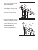
. IMPORTANT: To avoid damaging the Crossbar (107), do not use power tools and do not overtighten the #10 x 3/4" Screws (2). 12 First Orient the Crossbar (107) as shown. Attach the Crossbar to the Handrails (82, 83) with four #10 x 3/4" Screws (2) and four #10 Star Washers (12); do not tighten the Screws yet. 2 12 102 9 107 82 Insert the Console Frame (102) into the Handrails (82, 83). Attach the Console Frame with four 1/4" x 1" Patch Bolts (9); do not tighten the Patch Bolts yet.
14. Set the console assembly on the Left and Right Handrails (82, 83). Be careful not to pinch any wires. Insert the excess Upright Wire (87) into the Right Handrail. 14 Attach the console assembly to the Crossbar (107) with six #8 x 3/4" Screws (1). Start all six Screws, and then tighten each of them. Console Assembly 87 105 Attach the two Console Clamps (105) to the console assembly with four #8 x 1" Screws (53). 53 83 15. Hold the Right Upright Cover (86) against the console assembly.
16. Raise the Frame (55) to the position shown. Have a second person hold the Frame until this step is completed. 16 Orient the Storage Latch (51) so that the large barrel and the latch knob are oriented as shown. 55 Attach the Latch Bracket (6) and Storage Latch (51) to the Base (95) with two 3/8" x 2" Bolts (8) and two 3/8" Nuts (10). 10 Attach the upper end of the Storage Latch (51) to the bracket on the Frame (55) with a 3/8" x 2" Bolt (8) and a 3/8" Nut (10).
HOW TO USE THE CHEST PULSE SENSOR HOW TO PUT ON THE CHEST PULSE SENSOR The chest pulse sensor consists of two components: the chest strap and the sensor unit. Insert the tab on one end of the chest strap into the hole in one end of the sensor unit, as shown in the inset drawing. Press the end of the sensor unit under the buckle on the chest strap. The tab should be flush with the front of the sensor unit.
OPERATION AND ADJUSTMENT 2. If you are plugging in the power cord in Australia, go to step 3. THE PRE-LUBRICATED WALKING BELT Your treadmill features a walking belt coated with highperformance lubricant. IMPORTANT: Never apply silicone spray or other substances to the walking belt or the walking platform. Such substances will deteriorate the walking belt and cause excessive wear.
CONSOLE DIAGRAM FEATURES OF THE CONSOLE You can even listen to your favorite workout music or audio books with the consoleʼs stereo sound system while you exercise. The treadmill console offers an impressive array of features designed to make your workouts more effective and enjoyable. When you use the manual mode, you can change the speed and incline of the treadmill with the touch of a button. As you exercise, the console will display instant exercise feedback.
HOW TO TURN ON THE POWER 3. Start the walking belt. IMPORTANT: If the treadmill has been exposed to cold temperatures, allow it to warm to room temperature before turning on the power. If you do not do this, you may damage the console displays or other electrical components. Plug in the power cord (see page 16). Next, locate the power switch on the treadmill frame near the power cord. Press the power switch into the reset position.
6. Measure your heart rate if desired. • The incline level of the treadmill Note: If you use the handgrip pulse sensor and the chest pulse sensor at the same time, the console will not display your heart rate accurately. For information on the chest pulse sensor, see page 15. • The number of vertical feet you have climbed • The speed of the walking belt • Your heart rate (see step 6 on this page) The matrix offers several display tabs.
HOW TO USE AN ONBOARD WORKOUT During the workout, the profiles on the speed and incline tabs will Current Segment show your progress. The flashing segment of the profile represents the current segment of the workout. The height of the flashing segment indicates the speed or incline setting for the current segment. At the end of each segment, a series of tones will sound and the next segment of the profile will begin to flash.
If the speed or incline setting is too high or too low at any time during the workout, you can manually override the setting by pressing the Speed or Incline buttons; however, when the next segment of the workout begins, the treadmill will automatically adjust to the speed and incline settings for the next segment. To stop the workout at any time, press the Stop button. The time will begin to flash in the display. To resume the workout, press the Start button or the Speed increase button.
When you select an iFit Live workout, the display will show the duration of the workout, the distance you will walk or run, and the approximate number of calories you will burn. The display may also show the name of the workout. If you select a competition workout, the display will count down to the beginning of the race. 5. Start the workout. See step 3 on page 20. During some workouts, the voice of a personal trainer will guide you through your workout.
THE INFORMATION MODE The console features an information mode that keeps track of treadmill information and allows you to personalize console settings. To select the information mode, hold down the Stop button while inserting the key into the console and then release the Stop button. When the information mode is selected, the following information will be shown: The time display will show the total number of hours the treadmill has been used.
HOW TO FOLD AND MOVE THE TREADMILL HOW TO FOLD THE TREADMILL To avoid damaging the treadmill, adjust the incline to the lowest position before you fold the treadmill. Then, remove the key and unplug the power cord. CAUTION: You must be able to safely lift 45 lbs. (20 kg) to raise, lower, or move the treadmill. 1. Hold the metal frame firmly in the location shown by the arrow below. CAUTION: Do not hold the frame by the plastic foot rails. Bend your legs and keep your back straight.
TROUBLESHOOTING Most treadmill problems can be solved by following the simple steps below. Find the symptom that applies, and follow the steps listed. If further assistance is needed, see the front cover of this manual. PROBLEM: The power does not turn on SOLUTION: a. Make sure that the power cord is plugged into a properly earthed outlet (see page 16). If an extension cord is needed, use only a 3-conductor, 14-gauge (1 mm2) cord that is no longer than 5 ft. (1.5 m). b.
Remove the three #8 x 3/4" Screws (1) and carefully pivot the Motor Hood (62) off. 62 Locate the Reed Switch (73) and the Magnet (47) on the left side of the Pulley (48). Turn the Pulley until the Magnet is aligned with the Reed Switch. Make sure that the gap between the Magnet and the Reed Switch is about 1/8 in. (3 mm). If necessary, loosen the #8 x 3/4" Truss Head Screw (18), move the Reed Switch slightly, and then retighten the Screw. Reattach the Motor Hood (not shown) with the #8 x 3/4" Screws.
PROBLEM: The walking belt is off-center or slips when walked on SOLUTION: a. If the walking belt is off-center, first remove the key and UNPLUG THE POWER CORD. If the walking belt has shifted to the left, use the hex key to turn the left idler roller bolt clockwise 1/2 of a turn; if the walking belt has shifted to the right, turn the left idler roller bolt counterclockwise 1/2 of a turn. Be careful not to overtighten the walking belt.
EXERCISE GUIDELINES WARNING: Before beginning this Burning Fat—To burn fat effectively, you must exercise at a low intensity level for a sustained period of time. During the first few minutes of exercise, your body uses carbohydrate calories for energy. Only after the first few minutes of exercise does your body begin to use stored fat calories for energy. If your goal is to burn fat, adjust the intensity of your exercise until your heart rate is near the lowest number in your training zone.
SUGGESTED STRETCHES The correct form for several basic stretches is shown at the right. Move slowly as you stretch—never bounce. 1. Toe Touch Stretch Stand with your knees bent slightly and slowly bend forward from your hips. Allow your back and shoulders to relax as you reach down toward your toes as far as possible. Hold for 15 counts, then relax. Repeat 3 times. Stretches: Hamstrings, back of knees and back. 1 2. Hamstring Stretch Sit with one leg extended.
PART LIST—Model No. PETL10810.0 To locate the parts listed below, see the EXPLODED DRAWING near the end of this manual. Key No. Qty. 1 2 3 4 5 6 7 8 9 10 11 12 13 14 15 16 17 18 19 20 21 22 23 24 25 26 27 28 29 30 31 32 33 34 35 36 37 38 39 40 41 42 43 44 45 46 47 48 49 50 33 4 2 2 4 1 4 6 4 6 6 4 2 4 5 1 2 11 2 2 2 2 1 2 1 1 2 15 1 8 2 4 2 2 4 4 3 2 2 1 1 2 2 1 2 2 1 1 1 1 Description Key No. Qty.
Key No. Qty. 101 102 103 104 105 106 107 108 109 1 1 1 1 2 1 1 1 1 Description Key No. Qty. Console Console Frame Tray Module Housing Console Clamp Console Base Crossbar Access Door Electronic Bracket 110 111 112 113 114 115 116 * 1 1 2 1 1 1 4 – Description Filter Transformer Motor Bushing Motor Isolator Power Cord Adapter Chest Pulse Strap #8 x 1/2" Module Screw Userʼs Manual Note: Specifications are subject to change without notice.
24 34 33 19 56 30 28 61 18 59 36 60 21 41 30 24 42 40 34 33 19 28 18 18 39 36 18 58 57 21 32 43 18 30 56 30 55 20 44 36 30 46 18 10 54 45 30 49 48 47 8 42 18 18 51 32 20 39 30 43 36 10 23 30 8 10 45 46 6 8 EXPLODED DRAWING A—Model No. PETL10810.
EXPLODED DRAWING B—Model No. PETL10810.
EXPLODED DRAWING C—Model No. PETL10810.
EXPLODED DRAWING D—Model No. PETL10810.
ORDERING REPLACEMENT PARTS To order replacement parts, see the front cover of this manual.