
Operation Manual

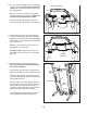


14. Hold the Right Upright Cover (86) against the
console assembly. Align the holes in the Right
Upright Cover with the holes in the Right Upright
(85). Attach the Right Upright Cover with two #8
x 3/4" Screws (1).
Attach the Left Upright Cover (80) to the Left
Upright (84) in the same way.
See steps 5 and 7. Tighten the four 3/8" x 4"
Patch Bolts (7) and the two 3/8" x 1 1/2" Patch
Bolts (3).
14
85
84
1
1
Console
Assembly
86
80
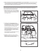
13. Set the console assembly on the Left and Right
Handrails (82, 83). Be careful not to pinch any
wires. Insert the excess Upright Wire (87) into
the Right Handrail.
Attach the console assembly to the Crossbar
(107) with six #8 x 3/4" Screws (1). Start all six
Screws, and then tighten each of them.
Attach the two Console Clamps (105) to the
console assembly with four #8 x 1" Screws (53).
13
83
105
53
87
1
1
1
Console Assembly
82
107
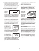
15. Raise the Frame (55) to the position shown.
Have a second person hold the Frame until
this step is completed.
Orient the Storage Latch (51) so that the large
barrel and the latch knob are oriented as shown.
Attach the Latch Bracket (6) and Storage Latch
(51) to the Base (95) with two 3/8" x 2" Bolts (8)
and two 3/8" Nuts (10).
Attach the upper end of the Storage Latch (51)
to the bracket on the Frame (55) with a 3/8" x 2"
Bolt (8) and a 3/8" Nut (10). Note: It may be
necessary to move the Frame back and forth to
align the Storage Latch with the bracket.
Lower the Frame (55) (see HOW TO LOWER
THE TREADMILL FOR USE on page 21).
15
51
95
10
Large
Barrel
8
55
10
6
8
Latch Knob
12