Model No. PETL69911.0 Serial No. Write the serial number in the space above for reference. USER’S MANUAL Serial Number Decal QUESTIONS? If you have questions, or if there are missing parts, please contact us: UNITED KINGDOM Call: 08457 089 009 From Ireland: 053 92 36102 Website: www.iconsupport.eu E-mail: csuk@iconeurope.com Write: ICON Health & Fitness, Ltd. c/o HI Group PLC Express Way CASTLEFORD WF10 5QJ UNITED KINGDOM AUSTRALIA Call: 1800 993 770 E-mail: australiacc@iconfitness.
TABLE OF CONTENTS WARNING DECAL PLACEMENT . . . . . . . . . . . . . . . . . . . . . . . . . . . . . . . . . . . . . . . . . . . . . . . . . . . . . . . . . . . . . . .2 IMPORTANT PRECAUTIONS. . . . . . . . . . . . . . . . . . . . . . . . . . . . . . . . . . . . . . . . . . . . . . . . . . . . . . . . . . . . . . . . . . 3 BEFORE YOU BEGIN. . . . . . . . . . . . . . . . . . . . . . . . . . . . . . . . . . . . . . . . . . . . . . . . . . . . . . . . . . . . . . . . . . . . . . . .5 PART IDENTIFICATION CHART.
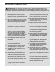
IMPORTANT PRECAUTIONS WARNING: To reduce the risk of serious injury, read all important precautions and instructions in this manual and all warnings on your treadmill before using your treadmill. ICON assumes no responsibility for personal injury or property damage sustained by or through the use of this product. 1. Before beginning any exercise program, consult your physician. This is especially important for persons over age 35 or persons with pre-existing health problems. same circuit.
20. Do not attempt to raise, lower, or move the treadmill until it is properly assembled. (See ASSEMBLY on page 7 and HOW TO FOLD AND MOVE THE TREADMILL on page 22.) You must be able to safely lift 45 lbs. (20 kg) to raise, lower, or move the treadmill. the treadmill, and before performing the maintenance and adjustment procedures described in this manual. Never remove the motor hood unless instructed to do so by an authorized service representative.
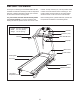
BEFORE YOU BEGIN Thank you for selecting the new PROFORM® 620 ZLT treadmill. The 620 ZLT treadmill provides an impressive selection of features designed to make your workouts at home more effective and enjoyable. manual. To help us assist you, note the product model number and serial number before contacting us. The model number and the location of the serial number decal are shown on the front cover of this manual. For your benefit, read this manual carefully before you use the treadmill.
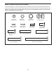
PART IDENTIFICATION CHART Use the drawings below to identify small parts used for assembly. The number in parentheses below each drawing is the key number of the part, from the PART LIST near the end of this manual. The number following the key number is the quantity used for assembly. Note: If a part is not in the hardware kit, check to see if it is preattached. Extra hardware may be included. 1/4" Star Washer (8)–2 M4.
ASSEMBLY • Assembly requires two persons. • To identify small parts, see page 6. • Place all parts in a cleared area and remove the packing materials. Do not dispose of the packing materials until you finish all assembly steps. • Assembly requires the following tools: the included hex keys one Phillips screwdriver • After shipping, there may be an oily substance on the exterior of the treadmill. This is normal.
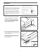
3. Identify the Right Upright (76), which is marked “Right.” Have a second person hold the Right Upright near the Base (74). 3 63 See the inset drawing. Tie the wire tie in the Right Upright (76) securely around the end of the Upright Wire (63). Then, insert the Upright Wire into the lower end of the Right Upright as you pull the other end of the wire tie through the Right Upright. Wire Tie 76 63 Wire Tie 76 74 4. Hold the Right Upright (76) against the Base (74).
5. Hold the Left Upright (66) against the Base (74). 5 Insert a 3/8" x 3 1/4" Screw (2) with a 3/8" Star Washer (3) into the top hole in the Left Upright (66). Then, partially tighten the Screw into the Base (74). Partially tighten two more 3/8" x 3 1/4" Screws (2) with two 3/8" Star Washers (3) into the Left Upright (66) and the Base (74); do not fully tighten the Screws yet. 66 74 2 6. Identify the Left and Right Upright Covers (88, 89).
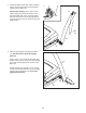
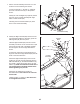
7. Set the console assembly face down on a soft surface to avoid scratching the console. 7 65 Loosen the four #8 x 1" Screws (7). Carefully pivot the Console Frame (61) to the position shown. 65 90 Identify the Left and Right Trays (90, 60). Attach the Trays to the console assembly with eight M4.2 x 13mm Screws (65). 60 7 Carefully pivot the Console Frame (61) back down to the console assembly. 61 8. Identify the Right Handrail (64). Remove the tie from the Right Handrail.
9. Have a second person hold the console assembly near the Right Upright (76). 9 Connect the Upright Wire (63) to the console wire. See the inset drawing. The connectors should slide together easily and snap into place. If they do not, turn one connector and try again. IF THE CONNECTORS ARE NOT CONNECTED PROPERLY, THE CONSOLE MAY BE DAMAGED WHEN THE POWER IS TURNED ON. Remove the long tie from the Upright Wire and the tie from the console wire. Then, insert the connectors into the Right Upright (76).
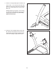
11. Slide the Right Upright Cover (89) up against the Right Handrail (64). Attach the Right Upright Cover with two M4.2 x 16mm Screws (56). Be careful not to overtighten the Screws. 11 Attach the Left Upright Cover (not shown) as described above. See steps 4 and 5. Tighten the six 3/8" x 3 1/4" Screws (2). 64 89 12. Have a second person hold the Frame (38) during the next three assembly steps. 56 12 Attach the Latch Crossbar (91) to the Frame (38) with two 1/4" x 1 3/4" Screws (96).
. Attach the Latch Bracket (99) on the end of the Storage Latch (97) to the Base (74) with two 3/8" x 2" Bolts (67) and two 3/8" Nuts (98). 13 74 98 99 97 14. Attach the upper end of the Storage Latch (97) to the Latch Crossbar (91) with a 3/8" x 1 3/4" Bolt (68) and a 3/8" Nut (98). 67 14 91 Move the treadmill to the desired location for use if you have not already done so (see HOW TO FOLD AND MOVE THE TREADMILL on page 22).
SP 2. See the inset drawing. Hold the receiver (A) so that the antenna (B) is oriented as shown. Peel the paper backing off the pad on the bottom of the receiver. Press the receiver onto the Access Door (80) as shown. 2 58 Connect the wire on the receiver to the indicated wire extending from the Console Base (58). Make sure that no wires are pinched. Reattach the Access Door (80) with the #8 x 3/4" Screw (4). Discard the other wires included with the receiver.
CONSOLE DIAGRAM Clip Key FEATURES OF THE CONSOLE automatically control the treadmill while the voice of a personal trainer coaches you through every step of your workout. To purchase iFit cards at any time, go to www.iFit.com or call the telephone number on the front cover of this manual. iFit cards are also available at select stores. The treadmill console offers an impressive array of features designed to make your workouts more effective and enjoyable.
HOW TO TURN ON THE POWER HOW TO USE THE MANUAL MODE IMPORTANT: If the treadmill has been exposed to cold temperatures, allow it to warm to room temperature before turning on the power. If you do not do this, you may damage the console displays or other electrical components. 1. Insert the key into the console. Plug in the power cord (see page 14). Next, locate the power switch on the treadmill frame near the power cord. Press the power switch into the reset position.
5. Change the incline of the treadmill as desired. the walking belt. Press the Display button repeatedly until the upper display shows the information that you are most interested in viewing. Note: While information is shown in the upper display, the same information will not be shown in the lower displays. To change the incline of the treadmill, press the Incline increase or decrease buttons or one of the numbered Incline buttons. Each time you press a button, the incline will change by 0.5 percent.
HOW TO USE A CALORIE WORKOUT ment, a series of tones will sound. If a different Current Segment speed and/or incline setting is programmed for the next segment, the speed and/or incline setting will flash in the display to alert you and the treadmill will automatically adjust to the new speed and/or incline setting. 1. Insert the key into the console. See HOW TO TURN ON THE POWER on page 16. 2. Select a calorie workout.
HOW TO USE A PERFORMANCE WORKOUT During the workout, the profile will show your Current Segment progress. The flashing segment of the profile represents the current segment of the workout. The height of the flashing segment indicates the speed setting for the current segment. At the end of each segment, a series of tones will sound.
HOW TO USE AN IFIT WORKOUT 3. Start the workout. To purchase iFit cards, go to www.iFit.com or call the telephone number on the front cover of this manual. iFit cards are also available at select stores. Press the Start button or the Speed increase button to start the workout. A moment after you press the button, the treadmill will automatically adjust to the first speed and incline settings of the workout. Hold the handrails and begin walking. 1. Insert the key into the console.
THE INFORMATION MODE mode, press the Speed decrease button. The console features an information mode that keeps track of the total distance that the walking belt has moved and the total number of hours that the treadmill has been used. The information mode also allows you to select a measurement system of miles or kilometers, and to turn on and turn off the display demo mode. To exit the information mode, remove the key from the console.
HOW TO FOLD AND MOVE THE TREADMILL HOW TO FOLD THE TREADMILL HOW TO MOVE THE TREADMILL Before folding the treadmill, adjust the incline to the lowest position. If you do not do this, you may damage the treadmill when you fold it. Remove the key and unplug the power cord. CAUTION: You must be able to safely lift 45 lbs. (20 kg) to raise, lower, or move the treadmill. efore moving the treadmill, fold it as described at B the left. CAUTION: Make sure that the latch knob is locked.
TROUBLESHOOTING Most treadmill problems can be solved by following the simple steps below. Find the symptom that applies, and follow the steps listed. If further assistance is needed, see the front cover of this manual. SYMPTOM: The console displays remain lit when you remove the key from the console a. The console features a display demo mode, designed to be used if the treadmill is displayed in a store. If the displays remain lit when you remove the key, the demo mode is turned on.
Locate the Reed Switch (33) and the Magnet (32) on the right side of the Pulley (31). Turn the Pulley until the Magnet is aligned with the Reed Switch. Make sure that the gap between the Magnet and the Reed Switch is about 1/8 in. (3 mm). If necessary, loosen the #8 x 3/4" Truss Head Screw (14), move the Reed Switch slightly, and then retighten the Screw. Carefully slide the Motor Hood (not shown) back on by lining up the guides. Reattach the Motor Hood with the five #8 x 3/4" Screws (not shown).
SYMPTOM: The walking belt is not centered between the foot rails. IMPORTANT: If the walking belt rubs against the foot rails, the walking belt may be damaged. SYMPTOM: The walking belt slips when walked on a. F irst, remove the key and UNPLUG THE POWER CORD. Using the hex key, turn both idler roller screws clockwise, 1/4 of a turn. When the walking belt is correctly tightened, you should be able to lift each edge of the walking belt 2 to 3 in. (5 to 7 cm) off the walking platform.
EXERCISE GUIDELINES Burning Fat—To burn fat effectively, you must exercise at a low intensity level for a sustained period of time. During the first few minutes of exercise, your body uses carbohydrate calories for energy. Only after the first few minutes of exercise does your body begin to use stored fat calories for energy. If your goal is to burn fat, adjust the intensity of your exercise until your heart rate is near the lowest number in your training zone.
PART LIST Model No. PETL69911.0 R0512A Key No. Qty. Description Key No. Qty.
14 45 44 11 10 43 19 14 14 20 29 14 96 27 91 14 28 14 11 46 14 42 14 20 19 14 18 30 14 96 14 14 14 20 19 77 1 41 14 14 39 104 34 31 25 14 98 40 32 24 33 68 14 14 35 14 18 19 86 30 25 97 28 24 17 37 4 20 1 77 38 102 103 98 102 100 101 1 22 36 67 EXPLODED DRAWING A Model No. PETL69911.
EXPLODED DRAWING B Model No. PETL69911.
EXPLODED DRAWING C Model No. PETL69911.
EXPLODED DRAWING D Model No. PETL69911.
ORDERING REPLACEMENT PARTS To order replacement parts, please see the front cover of this manual.