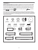
Model No. PETL69910.0 Serial No. Write the serial number in the space above for reference. USER’S MANUAL Serial Number Decal CUSTOMER CARE UNITED KINGDOM Call: 08457 089 009 From Ireland: 053 92 36102 Website: www.iconsupport.eu E-mail: csuk@iconeurope.com Write: ICON Health & Fitness, Ltd. c/o HI Group PLC Express Way CASTLEFORD WF10 5QJ UNITED KINGDOM AUSTRALIA Call: 1800 993 770 E-mail: australiacc@iconfitness.
TABLE OF CONTENTS WARNING DECAL PLACEMENT . . . . . . . . . . . . . . . . . . . . . . . . . . . . . . . . . . . . . . . . . . . . . . . . . . . . . . . . . . . . . . .2 IMPORTANT PRECAUTIONS. . . . . . . . . . . . . . . . . . . . . . . . . . . . . . . . . . . . . . . . . . . . . . . . . . . . . . . . . . . . . . . . . . 3 BEFORE YOU BEGIN. . . . . . . . . . . . . . . . . . . . . . . . . . . . . . . . . . . . . . . . . . . . . . . . . . . . . . . . . . . . . . . . . . . . . . . .5 ASSEMBLY . . . . . . . . .
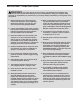
IMPORTANT PRECAUTIONS WARNING: To reduce the risk of serious injury, read all important precautions and instructions in this manual and all warnings on your treadmill before using your treadmill. ICON assumes no responsibility for personal injury or property damage sustained by or through the use of this product. 1. B efore beginning any exercise program, consult your physician. This is especially important for persons over age 35 or persons with pre-existing health problems. 10.
18. Never leave the treadmill unattended while it is running. Always remove the key, unplug the power cord, and press the power switch into the off position when the treadmill is not in use. (See the drawing on page 5 for the location of the power switch.) 22. Inspect and properly tighten all parts of the treadmill regularly. DANGER: Always unplug the power 23. 19. Do not attempt to raise, lower, or move the treadmill until it is properly assembled.
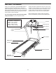
BEFORE YOU BEGIN Thank you for selecting the new PROFORM® 600 ZLT treadmill. The 600 ZLT treadmill offers a selection of features designed to make your workouts at home more effective and enjoyable. And when you’re not exercising, the treadmill can be folded up, requiring less than half the floor space of other treadmills. reading this manual, please see the front cover of this manual. To help us assist you, note the product model number and serial number before contacting us.
ASSEMBLY Assembly requires two persons. Set the treadmill in a cleared area and remove all packing materials. Do not dispose of the packing materials until assembly is completed. Note: The underside of the treadmill walking belt is coated with high-performance lubricant. During shipping, some lubricant may be transferred to the top of the walking belt or the shipping carton. This is normal and does not affect treadmill performance.
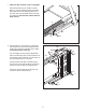
1. Make sure that the power cord is unplugged. 1 Remove the M10 Nut (19), the M10 x 50mm Bolt (31), and the shipping bracket (A) from the Base (95). Remove the shipping bracket from the other side of the treadmill. Discard the shipping brackets. Save the Nuts and the Bolts for steps 3 and 6. A 95 31 19 2. With the help of a second person, carefully tip the treadmill onto its left side. Partially fold the Frame (56) so that the treadmill is more stable; do not fully fold the Frame yet.
3. Attach a Wheel (97) with the M10 Nut (19), and the M10 x 50mm Bolt (31) that you removed in step 1. Do not overtighten the Nut; the Wheel must turn freely. 3 87 Press a Base Cap (87) into the Base (95). 31 19 4. Identify the Right Upright (89) and the Right Upright Spacer (91), which are marked with “Right” stickers. 97 4 Insert the Upright Wire (88) through the Right Upright Spacer (91) as shown. Then, set the Right Upright Spacer on the Base (95).
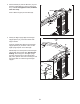
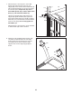
5. Hold a Bolt Spacer (90) inside the lower end of the Right Upright (89). Insert an M10 x 95mm Patch Bolt (8) with an M10 Star Washer (9) into the Right Upright and the Bolt Spacer. Repeat this step with a second Bolt Spacer (90), an M10 x 68mm Patch Bolt (114), and an M10 Star Washer (9). 5 89 8 114 9 Hold the Right Upright (89) against the Right Upright Spacer (91). Be careful not to pinch the Upright Wire (88).
7. With the help of a second person, hold a Bolt Spacer (90) inside the lower end of the Left Upright (85). Insert an M10 x 95mm Patch Bolt (8) with an M10 Star Washer (9) into the Left Upright and the Bolt Spacer. Repeat this step with a second Bolt Spacer (90), an M10 x 68mm Patch Bolt (114), and an M10 Star Washer (9). 7 8 114 85 9 Hold the Left Upright Spacer (86) and the Left Upright (85) against the Base (95).
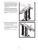
9. Set the console assembly face down on a soft surface to avoid scratching the console. 9 Loosen the four #8 x 1" Screws (107). Carefully pivot the Console Frame (111) to the position shown. Do not pivot the Console Frame too far or you will break the ground wire. 116 116 104 Identify the Left and Right Accessory Trays (104, 106). Attach the Accessory Trays to the console assembly with eight M4 x 13mm Screws (116).
11. Have a second person hold the console assembly near the Right Upright (89). 11 Console Assembly Connect the Upright Wire (88) to the console wire. See the inset drawing. The connectors should slide together easily and snap into place. If they do not, turn one connector and try again. IF YOU DO NOT CONNECT THE CONNECTORS PROPERLY, THE CONSOLE MAY BECOME DAMAGED WHEN YOU TURN ON THE POWER. Remove the long tie from the Upright Wire. Then, insert the connectors into the Right Upright (89).
. Slide the Right Upright Cover (110) up against the Right Handrail (101). Attach the Right Upright Cover with two M4 x 16mm Screws (124). Be careful not to overtighten the Screws. 13 Attach the Left Upright Cover (not shown) as described above. See steps 5 and 7. Tighten the two M10 x 95mm Patch Bolts (8) and the two M10 x 68mm Patch Bolts (114). 101 110 14. Raise the Frame (56) to the position shown. Have a second person hold the Frame until this step is completed.
If you purchase the optional chest pulse sensor (see page 23), follow the steps below to install the receiver included with the chest pulse sensor. 1. Make sure that the power cord is unplugged. Remove the five M4 x 19mm Screws (35) and the two M4 x 45mm Screws (2) from the back of the console assembly. 1 Console Assembly 35 2 2 35 35 2. Carefully lift the console assembly off of the Console Base (103). Locate the Pulse Wire (A) on the console assembly. 35 2 Console Assembly 103 A 3.
OPERATION AND ADJUSTMENT THE PRE-LUBRICATED WALKING BELT Follow the steps below to plug in the power cord. Your treadmill features a walking belt coated with highperformance lubricant. IMPORTANT: Never apply silicone spray or other substances to the walking belt or the walking platform. Such substances will deteriorate the walking belt and cause excessive wear. 1. P lug the indicated end of the power cord into the socket on the treadmill.
CONSOLE DIAGRAM Key Clip purchase iFit cards at any time, go to www.iFit.com or call the telephone number on the front cover of this manual. FEATURES OF THE CONSOLE The treadmill console offers an impressive array of features designed to make your workouts more effective and enjoyable. When you use the manual mode, you can change the speed and incline of the treadmill with the touch of a button. As you exercise, the console will display instant exercise feedback.
HOW TO TURN ON THE POWER HOW TO USE THE MANUAL MODE IMPORTANT: If the treadmill has been exposed to cold temperatures, allow it to warm to room temperature before turning on the power. If you do not do this, you may damage the console displays or other electrical components. 1. Insert the key into the console. Plug in the power cord (see page 15). Next, locate the power switch on the treadmill frame near the power cord. Press the power switch into the reset position.
5. Change the incline of the treadmill as desired. The lower right display—The lower right display can show the approximate number of calories that you have burned and the speed of the walking belt. The display also shows your heart rate when you use the handgrip pulse sensor (see step 7). To change the incline of the treadmill, press the Incline increase or decrease button or one of the numbered Incline buttons.
7. Measure your heart rate if desired. will flash each time your heart beats, one or two dashes will appear, and then your heart rate will be shown. For the most accurate heart rate reading, continue to hold the contacts for about 15 seconds. Note: If you use the handgrip pulse sensor and the optional chest pulse sensor at the same time, the console will not display your heart rate accurately. For information on the optional chest pulse sensor, see page 23.
HOW TO USE A CALORIE WORKOUT the flashing segment indicates the speed setting Current Segment for the current segment. At the end of each segment, a series of tones will sound. If a different speed and/or incline setting is programmed for the next segment, the speed and/or incline setting will flash in the display to alert you and the treadmill will automatically adjust to the new speed and/or incline setting. 1. Insert the key into the console. See HOW TO TURN ON THE POWER on page 17. 2.
HOW TO USE A PERFORMANCE WORKOUT 4. Select the duration of the workout if desired. 1. Insert the key into the console. If you have selected a performance workout, you can set the duration of the workout to a time between 15 and 45 minutes, in increments of 5 minutes. To set the duration of the workout press the Time increase or decrease button until the desired time is selected. See HOW TO TURN ON THE POWER on page 17. 2. Select a performance workout.
HOW TO USE AN IFIT WORKOUT 3. Start the workout. To purchase iFit cards, go to www.iFit.com or call the telephone number on the front cover of this manual. iFit cards are also available at select stores. Press the Start button or the Speed increase button to start the workout. A moment after you press the button, the treadmill will automatically adjust to the first speed and incline settings of the workout. Hold the handrails and begin walking. 1. Insert the key into the console.
THE INFORMATION MODE HOW TO USE THE STEREO SOUND SYSTEM The console features an information mode that keeps track of the total distance that the walking belt has moved and the total number of hours that the treadmill has been used. The information mode also allows you to select metric or English units of measurement, and to turn on and turn off the display demo mode.
HOW TO FOLD AND MOVE THE TREADMILL HOW TO FOLD THE TREADMILL HOW TO MOVE THE TREADMILL To avoid damaging the treadmill, adjust the incline to the lowest position before you fold the treadmill. Then, remove the key and unplug the power cord. CAUTION: You must be able to safely lift 45 lbs. (20 kg) to raise, lower, or move the treadmill. efore moving the treadmill, fold it as described at the B left. CAUTION: Make sure that the latch knob is locked in the storage position.
TROUBLESHOOTING Most treadmill problems can be solved by following the steps below. Find the symptom that applies, and follow the steps listed. If further assistance is needed, please see the front cover of this manual. PROBLEM: The power does not turn on SOLUTION: a. Make sure that the power cord is plugged into a properly earthed outlet (see page 15). If an extension cord is needed, use only a 3-conductor, 14-gauge (1 mm2) cord that is no longer than 5 ft. (1.5 m). b.
Remove the three M4.2 x 19mm Hood Screws (12) and carefully pivot the Motor Hood (67) off. 67 Locate the Reed Switch (70) and the Magnet (51) on the left side of the Pulley (53). Turn the Pulley until the Magnet is aligned with the Reed Switch. Make sure that the gap between the Magnet and the Reed Switch is about 1/8 in. (3 mm). If necessary, loosen the M4.2 x 19mm Screw (1), move the Reed Switch slightly, and then retighten the Screw. Reattach the Motor Hood (not shown).
PROBLEM: The walking belt is off-center or slips when walked on SOLUTION: a. If the walking belt is off-center, first remove the key and UNPLUG THE POWER CORD. If the walking belt has shifted to the left, use the hex key to turn the left idler roller bolt clockwise 1/2 of a turn; if the walking belt has shifted to the right, turn the bolt counterclockwise 1/2 of a turn. Be careful not to overtighten the walking belt. Then, plug in the power cord, insert the key, and run the treadmill for a few minutes.
EXERCISE GUIDELINES Burning Fat—To burn fat effectively, you must exercise at a low intensity level for a sustained period of time. During the first few minutes of exercise, your body uses carbohydrate calories for energy. Only after the first few minutes of exercise does your body begin to use stored fat calories for energy. If your goal is to burn fat, adjust the intensity of your exercise until your heart rate is near the lowest number in your training zone.
SUGGESTED STRETCHES The correct form for several basic stretches is shown at the right. Move slowly as you stretch—never bounce. 1. Toe Touch Stretch 1 Stand with your knees bent slightly and slowly bend forward from your hips. Allow your back and shoulders to relax as you reach down toward your toes as far as possible. Hold for 15 counts, then relax. Repeat 3 times. Stretches: Hamstrings, back of knees and back. 2. Hamstring Stretch Sit with one leg extended.
PART LIST Model No. PETL69910.0 R0413A To locate the parts listed below, see the EXPLODED DRAWING near the end of this manual. Key No. Qty. Description Key No. Qty. Description 1 2 3 4 5 6 7 8 9 10 11 12 13 14 15 16 17 18 19 20 21 22 23 24 25 26 27 28 29 30 31 32 33 34 35 36 37 38 39 40 41 42 43 44 45 46 47 48 49 50 M4.
Key No. Qty. Description Key No. Qty.
26 29 32 42 27 64 43 65 28 57 4 16 44 47 29 1 45 36 46 26 17 27 64 48 62 28 29 63 4 1 16 1 36 32 49 29 29 57 115 6 15 50 56 29 7 54 18 48 55 53 1 51 58 15 60 29 32 52 17 49 115 50 29 6 37 18 EXPLODED DRAWING A Model No. PETL69910.
EXPLODED DRAWING B Model No. PETL69910.
EXPLODED DRAWING C Model No. PETL69910.
EXPLODED DRAWING D Model No. PETL69910.
ORDERING REPLACEMENT PARTS To order replacement parts, please see the front cover of this manual.