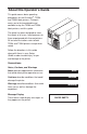
R t
P/N 136578–001, Rev B
US and CANADA Radio Interference Note This device complies with Part 15 of the FCC Rules. Operation is subject to the following two conditions: (1) this device may not cause harmful interference, and (2) this device must accept any interference received, including interference that may cause undesired operation. Properly shielded and grounded cables and connectors must be used in order to meet FCC emission limits.
Printronix, Inc. makes no representations or warranties of any kind regarding this material, including, but not limited to, implied warranties of merchantability and fitness for a particular purpose. Printronix, Inc. shall not be held responsible for errors contained herein or any omissions from this material or for any damages, whether direct, indirect, incidental or consequential, in connection with the furnishing, distribution, performance or use of this material.
This guide covers basic operating procedures for the Printronix. T3204 and T3304 label printers. Printronix wants you to feel comfortable and confident using the T3204 and T3304 label printers, and this guide. The guide has been designed to meet the needs of all users, from beginners to those experienced with thermal printers. All text and illustrations refer to both T3204 and T3304 printers except when noted.
BASIC OPERATING PROCEDURES Powering on the Printer . . . . . . . . . . . . . . . . . . . . . . . . . . . . . . . . . . . . . . . . . . . . . 1 Using the Primary Operator Panel . . . . . . . . . . . . . . . . . . . . . . . . . . . . . . . . . . . 1 Printing Modes . . . . . . . . . . . . . . . . . . . . . . . . . . . . . . . . . . . . . . . . . . . . . . . . . . . . 5 Loading Media . . . . . . . . . . . . . . . . . . . . . . . . . . . . . . . . . . . . . . . . . . . . . . . . . . . .
ii
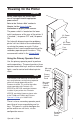
Before powering on the printer, make sure it is plugged into the appropriate power source. Refer to the “Select a Site” section in Chapter 2 of the Setup Guide for information on proper power sources. The power switch is located on the lower right–hand corner of the rear of the printer. It is marked for power OFF and | for power ON. For help with diagnosing printer problems, printer self–test routines are automatically run during the power–on cycle.
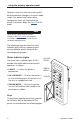
using the primary operator panel Selections from the main menu will need to be changed when changes in the print mode, media size, options and various other configuration items are required for the printer. Instructions begin on page 23 of this guide. Refer to the “Configuring the Printer” chapter in the Setup Guide for complete instructions in how to access and use the secondary operator panel.
using the primary operator panel CANCEL Function Cancels all jobs, if pressed when the printer is off line and not in a fault state. Also clears faults and puts the printer in the off line mode. Action With the printer off line, cancel the current run of labels by pressing once. Also, if a fault condition persists, press once to clear fault. Result The printer will then cancel all jobs and clear all imaged and buffered data.
using the primary operator panel ON LINE/PAUSE Function Temporarily stops the printing of labels and controls the on line/ off line status of the printer. Action ON LINE/ PAUSE To pause the printer, press once. The on line/pause indicator will blink. To place the printer in the on line mode, press once. The on line/ pause indicator will light. Result When the printer is paused, the print mechanism will stop when printing of the current label is completed. All data will be held in memory.
The printer is capable of printing in either of two modes: • Direct Thermal only (T3204–20 and T3304–20) • Direct Thermal and Thermal Transfer (T3204–21 and T3304–21) The two modes have in common the application of heat to produce the printed image.They differ in the way the heat is applied. In thermal transfer printing, the individual dot elements of the printhead apply heat to a ribbon.
Media Supply Window The printer accepts a wide range of media. It can be loaded with roll–fed, fan–folded, or die–cut continuous media of either thermal transfer or direct thermal type. Media width can range from 0.75 inches (19.1 mm) to 4.65 inches (118.1 mm). Media thickness can range from 0.0025 inches (0.0635 mm) to 0.01 inches (0.254 mm). Use the following procedures to load media of various kinds into the printer. Press ON LINE/PAUSE to place the printer in the off line mode.
Printers have been built with two types of standard media hubs: metal and plastic. From the diagrams below, follow the media loading instructions which match your printer. Do not use the media retainer if the media supply roll is wider than 4 inches. METAL HUB If you are using media with a 3” core, place the 3” media core adapters on the media hub assembly. Place the media supply roll on the media hub assembly.
To load fan–folded media, proceed as follows: Place the media supply either behind or beneath the printer, as shown. Media Hub Assembly Make sure the media feeds freely from the container. Media Retainer Route the media through the rear media loading slot. Continue with step 7. Route the media over the guide plate, under the media sensor and over the platen roller (located beneath the printhead).
10 If the media you are loading is of the same width as the current media, skip the next step and go on to step 12. 11 If you are loading media that is of a different width from the current media, you may need to adjust print quality as follows: note The printer is aligned at the factory with 4–mil–thick label stock, whose width is the maximum width accepted by the printer. a. Raise the hinge plate, and lower the printhead by rotating the printhead latch clockwise to the latched position.
Pull the head leveling knob outward, and rotate it one detent. Rotating the knob clockwise from position 1 will adjust the printer for media that is narrower than the maximum width accepted by the printer. When the head leveling knob is rotated clockwise from the detent position just before position 1 to position 1, the printhead will return to the maximum media width position. Head Leveling Knob Each of the 18 positions on the head leveling knob will raise or lower the printhead 0.
13 To use the media rewind hub, complete the following procedure. a. Lower the lower right-hand front panel. b. Remove the arc plate from its stored position, and install on the front of the printer. Route the media around the arc plate and to the media rewinder. c. Place the clasp over the end of the media, and rotate the media rewinder a few turns. Rotate the media guide up, and slide it to the media edge. d. Lift and snap the lower right-hand front panel closed. Continue with step 14.
The peel-and-present option allows for on-demand label dispensing. Although the peel-and-present mechanism is included with every printer, the label present sensor and internal rewind options are required to use this feature. To use the optional peel-and-present, follow the instructions outlined below. Turn off the printer, and open the side access cover. Rotate the printhead latch counterclockwise to raise the printhead. Lower the hinge plate and the lower front panel.
g. Route the media liner (backing) around the tear bar to the media rewinder. h. Place the clasp over the end of the media, and rotate the media rewinder a few turns. i. Rotate the media guide up, and slide it to the media’s edge. j. Lift and snap the lower right front panel closed. k. Raise the hinge plate, and latch the printhead by rotating the printhead latch clockwise to the latched position. l. Close the side cover.
Media Supply Window Use the following procedure to unload media from the printer. Press ON LINE/PAUSE to place the printer in the off line mode. Open the media supply door. Rotate the printhead latch counterclockwise to unlatch, and raise the printhead to an upright position. Media Supply Door Lower the hinge plate down. Slide the media guide to the outer edge, and rotate it to the down position.
To remove roll–fed media, proceed as follows: 3–Inch Core Adaptors Media Hub Assembly Roll the media onto the media hub or onto the rewind hub, as appropriate. If you have rolled the media onto the media hub, slide the roll of media off the hub. If you have rolled the media onto the rewind hub, lower the lower right-hand front panel.
Lower the lower right-hand front panel. Unroll the media from the hub, and remove the clasp. Lift and snap the lower right-hand front panel closed. Right-Hand Front Panel Rewind Hub Continue with step 8. Raise the hinge plate, and lower the printhead by rotating the printhead latch clockwise to the latched position. Close the media supply door.
Media Supply Window As noted previously, when printing in thermal transfer mode, the printer requires a ribbon. Use the following procedure to install a new ribbon. The thermal transfer mode is selected through the printer menu system. The main menu is accessed via the secondary operator panel. Refer to the “Configuring the Printer” chapter in the Setup Guide for complete instructions in how to access and use the secondary operator panel.
Ribbon Supply Roll Supply Hub Take-Up Hub J-Hook Make sure the ribbon roll is pushed up against the hub flange. Route the ribbon to the take-up hub, as shown. 18 While holding the ribbon take-up hub, rotate the J-hook clockwise to unlatch it.
Raise the J-hook upward, and place the end of the ribbon over the take-up hub. Slide the J-hook back into place, as shown. While holding the ribbon take-up hub, rotate the J-hook counterclockwise to latch. Turn the take-up hub until all the ribbon slack is removed. Raise the hinge plate, and lock the printhead by rotating the printhead latch clockwise. Printhead Latch Hinge Plate Close the media supply door. Press ON LINE/PAUSE to enable printing.
Generally, ribbons are used to completion and then replaced. Removal of the old ribbon is simply a matter of pulling it off the take–up hub and discarding it. However, there may be times when the use of direct thermal media is required and an installed ribbon has not been completely used up. (As noted previously, when printing in direct thermal mode, the printer does not use a ribbon.) In this case, use the following procedure to remove the ribbon.
Ribbon Supply Roll Supply Hub Take-Up Hub J-Hook Printhead CUT Cut the ribbon anywhere between the take-up hub and the printhead. Rotate the printhead latch counterclockwise to raise the printhead, and then lower the hinge plate. While holding the ribbon take-up hub, rotate the J-hook clockwise to unlatch it.
Slide the used ribbon off the hub, and dispose of it. Turn the ribbon supply hub clockwise to draw the unused portion of the ribbon back onto the supply roll. You may leave the unused portion of the ribbon in place until the next thermal transfer print job, at which time you may reinstall it by following the ribbon installation procedure. 22 Raise the hinge plate, and lock the printhead by rotating the printhead latch clockwise. Close the media supply door.
PRINT MODE selects the printing mode of the printer. Selecting DIRECT THERMAL MODE activates direct thermal printing mode (ribbon must not be installed). Selecting THERMAL XFER activates thermal transfer printing mode (ribbon required). Press ON LINE/PAUSE to place the printer in the off line mode. Press twice to enter the paper OFFLINE IGP/PGL PAPER CONTROL Page Width control menu. Press until the print mode PAPER CONTROL Print Mode menu is displayed.
Selecting Gap Sensor GAP SENSOR selects the type of media used for printing. The options for this selection are as follows: • TRANSMISSIVE (see–through) • REFLECTIVE (black stripe) • NONE (default) Press ON LINE/PAUSE to place the printer in the off line mode. Press to enter the configuration menus. Press to reach the printer control menu. Press to enter the printer control menu. Press to reach the gap sensor menu. Press Press to enter the gap sensor menu.
The PRINT INTENSITY adjustment is used to balance a new printhead, so that it prints at the same level of darkness as did the previous head. You can specify intensity values from –10 through +10. The factory default setting is 0. Press ON LINE/PAUSE to place the printer in the off line mode. Press to enter the configuration OFFLINE IGP/PGL USER CONFIG PAPER CONTROL menus. Press to reach the printer control USER CONFIG PRINTER CONTROL menu.
The options for this selection are as follows: • SELF STRIP – selects the self strip option. When the label present sensor is installed and enabled, the printer can be configured for “one up” printing. • CUTTER selects the cutter mechanism option. The cutter must be installed to use this option. • TEAR OFF –selects the tear off option. • CONTINUOUS – selects the continuous feed option. Press ON LINE/PAUSE to place the printer in the off line mode.
Press to enter the media handling Media Handling Continuous * menu. Press to view the desired Media Handling Continuous option. Media Handling Tear Off Media Handling Cutter Media Handling Self Strip Press ENTER to select the desired option. Media Handling Self Strip * Press ON LINE/PAUSE to place the printer in the on line mode.
Selecting the Ribbon Saver RIBBON SAVER selects the ribbon saver option, if the ribbon saver is installed. Press ON LINE/PAUSE to place the printer in the off line mode. Press to enter the configuration menus. Press to reach the printer control menu. Press OFFLINE IGP/PGL USER CONFIG PAPER CONTROL USER CONFIG PRINTER CONTROL to enter the printer control PRINTER CONTROL Media Handling to reach the ribbon PRINTER CONTROL Ribbon Saver menu. Press saver menu.
Keeping the printer clean will help ensure efficient operation and good print quality. warning Media Supply Window Disconnect the AC power cord before cleaning the printer. Cleaning the Outside of the Cabinet Clean the outside of the cabinet with a soft, lint–free cloth and mild detergent (dishwashing liquid works well). Do not use abrasive powders or chemical solvents. Clean the window with plain water or a mild window cleaner.
Using a soft–bristled, non–metallic brush, remove dust particles from the media path, ribbon guides and ribbon path. Cotton Swab Brush and vacuum accumulated dust or residue, especially in the printhead areas. Using a cloth dampened with anhydrous alcohol, clean the ribbon guides, rollers and mechanical assemblies. The printhead will require cleaning after extended normal operation. Regular cleaning will ensure the highest print quality.
If a printer fault occurs, a specific message appears in the message display. When this happens, correct the fault immediately. You can correct most faults by performing a simple procedure, such as clearing a media jam or reloading media or ribbon. For more serious faults, however, call an authorized Printronix service representative. PROM Fault PROM FAULT Power–up initialization test detected a PROM failure. Contact your authorized service representative.
Paper Jam PAPER JAM Possible causes: • Improper media. • Actual label length greater than programmed label length. Paper Empty PAPER EMPTY Printer is out of media stock. Media Fault MEDIA FAULT The ribbon system detected a fault. Possible causes: • Out of ribbon. • Ribbon motion was stopped. • Obstructions in the media movement. • Paper motion stopped. Cutter Fault CUTTER FAULT The cutter operation failed. Possible causes: • Cutter is jammed. • Defective cutter hardware.
"% " & $ & $ & #% % % " " ! & ! #" !" " ! #" #!" !" " ! & $ ! " # % ! " " http://www.printronix.