
CD Color Printer II User's Manual

46 Interfacing Information
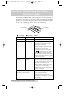
14
25 13
PIN 1
36 18
PIN 119
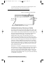
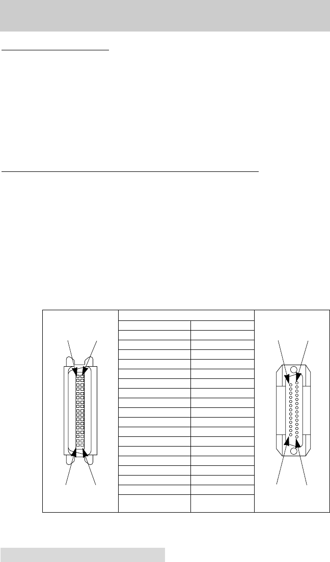
WIRE DIAGRAM
DB36P DB25P
11
22
33
44
55
66
77
88
99
10 10
11 11
12 12
13 13
14 14
32 15
31 16
36 17
THROUGH 3019 THROUGH 25
SHELL SHELL
TABLE A-1: Parallel Interface Pin Assignments
Appendix A: Interfacing Information
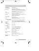
A. INTRODUCTION
The CD Color Printer is equipped with both a standard 8-bit
centronics-type parallel interface port and a high-speed serial
interface port. These communication ports are the means
through which the printer receives data from your computer.
This section describes the pin assignments and signal
specifications for each of these ports as well as for the printerÕs
auxiliary interface port.
B. CENTRONICS-TYPE PARALLEL INTERFACE
The Centronics-type parallel interface is the most widely
used printer interface due to its simplicity, speed, and
standardization throughout the computer industry. The
printerÕs parallel interface connector is a standard 36-pin Amp
type with two metal-wire retaining clips. It mates with a
standard computer to printer parallel cable. For best results,
always use a shielded, bi-directional parallel cable which is
less than 6 feet in length.
Pin assignments are as follows:
510198 Fargo/CD Color PrtrII 2/26/99 12:36 PM Page 46