
Installation manual

-95-
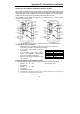
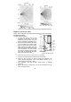
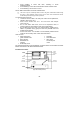
Vertical Adjustment
To position the PCB, turn the Easy Lock counter-clockwise and slide the PCB up or down to
the required setting using the vertical adjustment scale. The detector’s coverage area is 14m
x 14m (EL-2600/EL-2645) or 12m x 12m (EL-2600PI/EL-2645PI) when the PCB is positioned
at 0. Slide the PCB up towards the -8 position to decrease the coverage area bringing the
beams closer to the mounting wall.
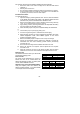
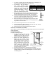
Walk Test Mode
A walk test is performed in order to determine the lens coverage pattern of the detector – see
Figure B.2. Walk Test mode cancels the delay time between detections, enabling you to
perform an efficient walk test.
To perform a Walk Test.
1. Place the Mode jumper over pins 1 & 2.
2. Walk across the scope of the detector according to the detection
pattern selected.
3. Confirm that the LED activates and deactivates accordingly. Wait five
seconds after each detection before continuing the test.
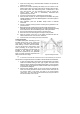
4. After completing the walk test, remove the jumper and place it over
one pin for storage – see Mode Jumper Safeguard.
LED Indication
The LED indicator is lit twice every time a transmission is made. To enable or disable LED
indication, refer to Table B.4 below.
LED Indication EL-2600/EL-2600PI EL-2645/EL-2645PI
Disabed Remove LED Jumper DIP-Switch 1 OFF
Enabled Install LED Jumper DIP-Switch 1 ON
Table B.4: LED Indication Settings
,
The LED should only be disabled after successfully walk testing the detector.
Mode Jumper Safeguard
During normal operation, the Mode jumper should be placed over one pin for storage. When
the mode jumper is placed over two pins, the detector is either in Radio or Walk Test Mode.
As a precaution, these modes are limited to three minutes. After three minutes have expired,
the detector switches back to normal operation. If this happens, you can reset a mode by
removing and replacing the mode jumper.