
Installation manual

-94-
For maximum pet immunity the following guidelines are recommended:
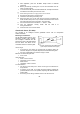
• Mount the center of the unit at a height of 2m with the PCB vertical
setting at -4.
• Set the pulse counter to 2.
• Do not aim the detector at stairways that can be climbed by an animal.
• Avoid a location where an animal can come within 1.8m of the detector
by climbing on furniture, boxes or other objects.
Installation Procedure
To install PIR sensors:
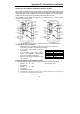
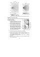
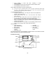
1. Open the housing by removing the front cover. To do so, insert a screwdriver
in the release slot (located at the bottom of the detector between the front
and back cover). Turn the screwdriver 90º to release the cover.
2. Remove the PCB by turning counter-clockwise and removing the Easy
Lock – do not touch the face of the pyro sensor!
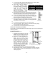
3. Apply battery power by removing the isolator that separates the battery
from the contacts on the battery holder.
4. Place the Mode jumper over pins 2 & 3 (Radio Mode); the LED flashes.
,
Install the Mode jumper only after applying battery power.
5. From the Programming menu, select Devices, Zones [911].
6. Select the zone to which you want to register the transmitter; the system
initiates Registration mode. When Save? appears on the control
system’s LCD display, press .
7. Remove the Mode jumper and place it over one pin for storage.
8. Choose an appropriate mounting height from Table B.1 and test the
transmitter from the exact mounting position before permanently
mounting the unit.
9. Knock out the mounting holes and attach the base to the wall.
10. Mount the PCB at the required vertical adjustment and replace
the PCB screw.
11. Write the number of the zone on the sticker provided. Affix the sticker
inside the front cover for future reference and replace the front cover.
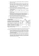
Warm-Up Time
The detector will need to warm up for the first 90
seconds after applying power.
Pulse Counter
The pulse counter determines the amount of
beams that need to be crossed before the
detector will generate an alarm. To set the pulse
counter, refer to tables B.2 and B.3.
Adaptive Pulse Count (EL-2645/EL-2645PI)
Using the Adaptive pulse count feature, the
detector chooses between 1 or 2 pulses based
on its analysis of the received signal.
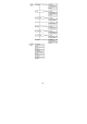
Jumper Position Pulse Count
Pins 1&2 1
Pins 2&3 2
Jumper Removed 3
Table B.2: Pulse Count Jumper (EL-2600/EL-2600PI)
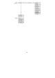
Switch 2 Switch 3 Pulse Count
OFF OFF 1
ON OFF 2
ON ON 3
OFF ON Adaptive
Table B.3: Pulse Count Setting (EL-2645/EL-2645PI)