
Installation manual

-17-
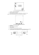
4. Place the control system in position against the wall and mark the
upper and lower mounting holes. If using the back tamper, also mark
the hole for the back tamper screw.
5. Install wall anchors in the appropriate positions.
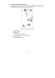
6. Thread any required cables through the wiring hole on the back
cover (e.g. AC power and telephone line) and make any
necessary wiring connections.
7. Connect the power cable to the AC power input on the Main board –
see 1.4.1: The Main Board.
8. Connect the telephone line to the Telephone Line terminal block on the
PSTN module – see 1.4.2: PSTN Module.
9. Connect any additional hardwire LCD keypads if required – see 2.4:
Installing Hardwire LCD Keypads.
10. Mount the control system to the wall using four screws and insert the
back tamper screw if required – see 2.3: Back Tamper.
,
The control system shall be mounted so that it shall withstand a force of at least three
times its own weight.
11. Replace the Main Board and reconnect its peripheral modules.
12. Connect the flat cable connecting the Main board to the front panel
keypad and the replace the front cover’s fastening bands.
13. Apply AC power.
,
Always connect AC power before connecting the battery pack. Batteries are supplied
uncharged. When you first connect the battery, it is probable that the system will display a
Low Battery condition. Allow the battery to charge for at least 18 hours before use.
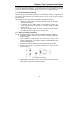
14. Connect the battery pack to the connector on the Main Board.
15. Position the front cover’s top holding hooks onto the back cover and
snap the front cover closed.
16. After installing the control system, perform the Find Modules function –
see 12.5: Find Modules.
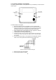
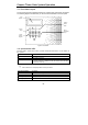
2.3: Back Tamper
The back tamper switch is an optional feature that provides an
extra safeguard in the event that the control system is removed
from the wall.
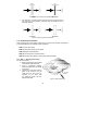
The back tamper switch is located on the rear side of the control
system’s Main Board and is constantly depressed by the section
of the back cover shown in Figure 2.6.
For this feature to operate, you must insert a screw into the back tamper mounting hole –
see 2.2.5: Step 5 – Installing the Control system and Transmitters. When the control system
is removed from the wall, the screw causes the perforated section of the plastic to break
and remain attached to the wall. As a result, the back tamper switch is released and an
alarm is generated.
Figure 2.6: Perforated
Back Tamper Release