
Installation manual

-11-
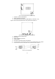
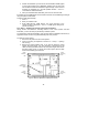
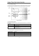
Figure 1.5: Home Automation Module (with internal PLI)
1. Interface connector to Main Board
2. Flash programming connector
3. Power-line terminal connections to Main Board (1 - Neutral; 2 - Live)
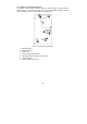
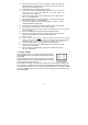
Figure 1.6 shows the HA module used in the systems with external PLI.
Figure 1.6: Home Automation Module (with external PLI)
1. Interface connector to Main board
2. Status LED
3. Flash programming connector
4. Jumper header
5. Connector to the external power-line interface
,
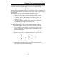
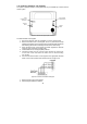
For external X10 PLI, we recommend to use the two way TTL/CMOS interface such as XM10E
module connected to the HA module with an RJ11 cable wired as shown on figure 1.7.
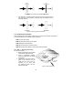
Figure 1.7: RJ11 wiring diagram