infinite prime Installation Manual - Version 4.00 Catalog Number: ZI0644A (11/2008) All data is subject to change without prior notice. Hereby, Electronics Line 3000 Ltd. declares that this control system is in compliance with the essential requirements and other relevant provisions of Directive 1999/5/EC. Copyright © 2008 Electronics Line 3000 Ltd. All rights reserved.
Table of Contents Chapter One: Introduction.............................................................................................................................5 1.1: Documentation Conventions ...........................................................................................................5 1.2: Specifications ..................................................................................................................................6 1.3: System Overview .............................
9.1: Swinger Setting .............................................................................................................................57 9.2: Code Lockout ................................................................................................................................57 9.3: Arm/Disarm Options ......................................................................................................................57 9.4: Panic Alarm.....................................................
Chapter One: Introduction This manual is designed to help you install the infinite prime control system. We strongly urge you to read through this manual, in its entirety, before beginning the installation process so that you can best understand all that this security system has to offer. This manual is not intended for end user use. End users are encouraged to read the user manual provided with the system.
1.
Central station communication and up/downloading employ either regular PSTN or high-speed cellular communication. SMS messaging provides an innovative method used for both central station and Follow-me user monitoring. Additionally, SMS messages can be sent to the control system enabling the user to send commands to the system from anywhere on the planet. The control system’s home automation capabilities provide a wealth of features.
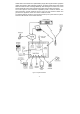
1.4: Hardware Layout The aim of this section is to acquaint you with the various circuit boards that make up the system. Apart from the Main Board, each peripheral module is available as an optional extra designed for installation inside the plastic housing. Figure 1.2: System Layout 1. 2. 3. 4. 5.
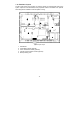
1.4.1: The Main Board The Main Board is the brain of the system and connects to various peripheral modules using a number of interface connectors. Additionally, the Main Board includes a programmable output, a hardwire zone input and a USB port for PC programming. Figure 1.3: Main Board 1. 2. 3. 4. 5. 6. 7. 8. 9. 10. 11. 12. 13. 14. 15. 16. 17. 18. 19. 20. 21. 22.
1.4.2: PSTN Module The PSTN module provides the system with a standard dialer for communication via the Public Switched Telephone Network (PSTN). , Do not use VoIP phone lines for communication to the central monitoring station. In certain cases the system may not transmit alarm signals successfully over the VoIP network. Alternative Telephone Line Socket Option Figure 1.4: PSTN Module 1. 2. 3. 4. 5. 6.
Figure 1.5: Home Automation Module (with internal PLI) 1. Interface connector to Main Board 2. Flash programming connector 3. Power-line terminal connections to Main Board (1 - Neutral; 2 - Live) Figure 1.6 shows the HA module used in the systems with external PLI. Figure 1.6: Home Automation Module (with external PLI) 1. 2. 3. 4. 5.
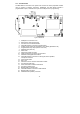
1.4.4: Cellular Communications Module The Cellular Communications module enables the control system to communicate via cellular networks. This offers the ability to send or receive SMS messages, perform up/downloading, implement cellular 2-way voice applications. Figure 1.8: Cellular Communications Module 1. 2. 3. 4. 5. 6. 7.
Chapter Two: System Installation The following chapter explains how to install the system and provides guidelines and tips on how to optimize the installation. It is recommended that you familiarize yourself with the various circuit boards that make up the system – see 1.4: Hardware Layout. 2.1: Pre-Installation Planning Before starting the installation procedure, it is worthwhile to draw a rough sketch of the building and determine the required position for the control system and each wireless device.
Figure 2.2: Considering Construction Materials • The reduction of the RF signals’ strength is directly proportional to the thickness of the obstacle, assuming that the obstacles are of identical material. Figure 2.3: Considering Thickness of Obstacles 2.2: Installation Procedure After unpacking the kit and making certain that you have all the necessary equipment, it is recommended that you install the system as follows: STEP 1: Open the housing. STEP 2: Temporarily power up the system.
2.2.2: Step 2 – Powering Up the System In order to register and test transmitters, it is necessary to temporarily power up the system before installing the control system. At this stage, do not connect the backup battery. Thread the power cable through the wiring hole on the back cover and connect the cable to the AC power input on the Main board. For the exact location of the AC power input, see 1.4.1: The Main Board. Close the front cover and apply AC power.
4. 5. Activate the transmitter you wish to test; the transmitter’s details appear on the control system’s LCD. Additionally, between one and four tones are sounded to indicate the transmitter’s signal strength. If four tones are sounded, the transmitter is in the best possible location – see 4.7.7: Transmitters for further information. After you have tested each transmitter, press to exit TX Test mode.
4. 5. 6. 7. 8. 9. 10. Place the control system in position against the wall and mark the upper and lower mounting holes. If using the back tamper, also mark the hole for the back tamper screw. Install wall anchors in the appropriate positions. Thread any required cables through the wiring hole on the back cover (e.g. AC power and telephone line) and make any necessary wiring connections. Connect the power cable to the AC power input on the Main board – see 1.4.1: The Main Board.
2.4: Installing Hardwire LCD Keypads The system supports hardwire LCD keypads that may be installed up to 300m from the control system. LCD Contrast Potentiometer Flash Programming Connector Terminal Block Tamper Switch Figure 2.7: Hardwire LCD Keypad (back cover off) To install hardwire LCD keypads. 1. Disconnect all power, both AC and battery, from the control system. 2. Remove the back cover of the keypad.
a. b. 9. 10. Make certain the keypad’s tamper switch is open. On the keypad, press keys 1, 3 and 5 simultaneously. c. Use the arrow keys ( / ) to select the keypad address. d. Press . Position the front cover’s top holding hooks onto the back cover and snap the front cover closed. After installing hardwire keypads, perform the Find Modules function – see 12.5: Find Modules.
Chapter Three: Basic System Operation 3.1: Front Panel Layout The front panel provides a detailed interface for operating and programming the system. The following diagram will familiarize you with the various elements on the front panel. LCD Display System Status LEDs Arming Keys Menu Navigation Keys Alphanumeric Keypad Figure 3.1: Front Panel 3.2: System Status LEDs The two LEDs, Armed and Power, provide essential information on the status of the system.
3.3: Front Panel Keypad The alphanumeric keypad on the front panel enables you to perform various operation and programming tasks. Apart from the regular functions of a standard alphanumeric keypad, the keypad offers a number of special functions. These functions are listed in the following table. Key 1 0 Special function Used to enter symbols in descriptor editing. Used to enter symbols in descriptor editing. Used to cancel the current selection. Used to return to the previous menu level.
This… DISARMED FULL ARMED PART ARMED PERIMETER ARMED FULL ARMING PART ARMING PERIMETER ARMING PART ARMED INST PERIM ARMED INST PART ARMING INST PERI ARMING INST Means… The system is disarmed. The system has been armed using the displayed arming method. The system is in the process of arming (displayed during exit delay). The system has been armed using the displayed arming method with the Instant arm feature activated. The system is in the process of arming with the Instant arm feature activated.
3.6: Hardwire LCD Keypad In addition to the front panel keypad, you can install up to three, individually addressed, hardwire LCD keypads (or two keypads with large LCD). The layout of the hardwire LCD keypad is similar to the front panel keypad and most of the functionality is identical. The following diagram shows the layout of the hardwire LCD keypad. LCD Display System Status LEDs Menu Navigation Keys Alphanumeric Keypad Arming Keys Menu Navigation Keys Figure 3.
3.7: Arming/Disarming The following section explains how to arm and disarm the control system using the LCD keypad. The infinite prime offers three arming modes that you can define to suit the application. Figure 3.4 illustrates the three arming modes. In each diagram, the protected area is shaded. Full Part Perimeter Figure 3.4: Arming Modes The arming options are entirely flexible. You can program each sensor to be included in any combination of the three arming modes – see 7.6.2: Arm Set.
To partially arm the system using the hardwire LCD keypad: 1. Check if the system is ready to arm. 2. Press PART on the keypad. 3. Select Part arming. 4. If One-Key Arming is disabled, enter your user code. 3.7.4: Perimeter Arming Perimeter arming is designed for when the occupant intends to remain inside the premises and secure the perimeter. To arm the system’s perimeter using the front panel keypad: 1. Check if the system is ready to arm. 2. Press the Perimeter arming key on the keypad. 3.
3.7.6: Forced Arming Forced arming enables you to arm the system when the system is not ready. For example, if a door protected by a magnetic contact is open, you may arm the system on condition that the door will be closed by the end of the Exit delay. If the door is still open after the exit delay expires, an alarm is generated. Two conditions enable you to perform Forced arming: • Forced arming is enabled – see 9.3.1: Forced Arm.
, While the SMS Command Descriptor is optional, you must start the SMS command with the # symbol for the system to accept the command. After an SMS command is executed by the system, you can program the system to return a confirmation message to the sender – see 10.7.5: SMS Confirmation. 3.8.1: Arm Status Reply On receiving an Arm Status request message, the system returns a status message to the sender.
Figure 3.8: Fire Alarm Activation To activate a Medical alarm from the front panel or hardwire LCD keypad: • Press keys 4 and 6 simultaneously. Figure 3.
Chapter Four: Advanced System Operation Besides the basic arming functions described in the previous chapter, you can access additional functions via the menu. This chapter describes these functions and the menu navigation procedure. 4.1: Menu Navigation Alphanumeric Keypad Menu Navigation Keys HA Off Key HA On Key Service Call Key Figure 4.
4.3: Sensor Bypassing/Unbypassing When a sensor is bypassed, it is ignored by the system and does not generate an alarm when triggered. To bypass or unbypass a sensor: 1. From the Bypass Zones menu, select Bypass/Unbyp. [21]. 2. Using the arrow keys, scroll to the sensor you want to bypass or unbypass. 3. Press to change the bypass status. 4. Press ; Save Changes? is displayed. 5. Press to confirm the changed bypass status. To unbypass all sensors: 1.
Code 28: Duress Code The Duress code is designed for situations where the user is being forced to operate the system. This user code grants access to the selected operation, while sending a Duress event message to the central station. Code 29: Telecontrol Code The Telecontrol code is designed to enable the user to perform a number of tasks via their telephone using DTMF commands.
4.4.3: User Code Descriptors Each user code can be assigned a 16-character descriptor. These descriptors help to identify users in the event log and in SMS Follow Me messages. To edit a code descriptor: 1. From the main menu, select User Codes [4]. 2. Select a code. 3. From the code’s sub-menu, select Descriptor [#2]. 4. Edit the descriptor using the alphanumeric keypad. 5. Press when you have finished editing. 4.
Figure 4.2 shows the detailed event log entry for a Fire alarm on November 14th 2003. The event was successfully reported to the central station. 4.6.1: Event Log Authorization Levels Every event that occurs is recorded in the event log. However, certain events are intended for the installer only. Those events include various service messages that are of little interest to the regular user. The View Log function requires you to enter either the Master or Installer code.
To record a message: 1. From the Service menu, select Messages, Record Message [7022]. 2. Press to start recording the message. 3. Record your message. The message may be up to twenty seconds long. 4. Press to stop recording; the message is automatically played back and OK? is displayed. 5. Press to save your recording. To delete a message: 1. From the Service menu, select Messages, Delete Message [7023]; OK? is displayed. 2. Press ; the message is deleted.
To view the TX list: 1. From the Service menu, select Transmitters, TX List [7071]; the first transmitter on the list is displayed. 2. Using the arrow buttons, scroll through the transmitter list. 3. When you have finished viewing, press to exit the list. The TX list displays the following information for each transmitter: • The zone/device number or descriptor. Press the key to toggle the display. • The signal strength of the last received transmission.
Press… 1 4 3 6 To… Increase microphone sensitivity Reduce microphone sensitivity Increase speaker volume Reduce speaker volume Table 4.3: Voice Level Adjustment 4. Press ; the new settings are stored in the memory. 4.7.9: GSM Signal Strength You can measure the GSM signal strength using the system’s RSSI (Received Signal Strength Indication) meter. This function enables you to calculate the optimal location to install the control system with the Cellular Communications module.
Chapter Five: Telecontrol and Two-Way Audio The infinite prime control system offers a range of Telecontrol features that provide remote access via the telephone. These features include Two-Way Audio, remote arming/disarming and cancel siren activation. This chapter explains these features and their operation procedures. Telecontrol features can be separated into two fundamental groups; incoming and outgoing calls. These groups differ in their associated features. 5.
To make a Telecontrol call: 1. Call the control system either using the double call method (PSTN) or directly (Cellular); when the control system picks up, two DTMF tones are sounded. 2. Enter the Telecontrol code (Code 29) on your telephone within 15 seconds. , 3. , , , , 4. 5. Do not enter your user code until you hear the two DTMF tones. Any digits entered before the tones are sounded are disregarded by the system. A DTMF tone is sounded to indicate that the system is ready to receive commands.
5.1.6. HA and PGM DTMF commands During a Telecontrol call, you can turn On and Off the Home Automation units, activate and deactivate PGM using the DTMF commands “4XX” (PGM/HA unit #XX On) and “5XX” (PGM/HA unit #XX Off). 5.1.7: Siren Muting The siren is muted during Two-Way Audio communication. At the end of the call, the siren is re-activated (if the Siren Cut-Off has not yet expired). During the call, pressing “9” on your telephone cancels the re-activation of the siren. 5.1.
5.2.2: TWA Alarm Reporting In the event of Burglary, Fire and Medical alarms, the control system is able to report the events and then stay on the line after ACK 2 is received. This allows the operator to verify the alarm or provide assistance in the event of an emergency. For this feature to function, you must enable Two-Way Audio for both the account and the event group. The sequence for Two-Way Audio during alarm reporting is as follows: 1.
5.2.4: TWA Follow-Me The TWA Follow-Me feature is designed to establish a Two-Way Audio connection with the user in the event of an alarm. For this feature to function, the account’s protocol must be defined as TWA Follow-Me. The sequence for a Two-Way Audio Follow-me call is as follows: 1. An alarm occurs. 2. The control system dials the programmed telephone number and sounds two DTMF tones when you pick up the call. 3. Press "2" on your telephone; the control system opens the audio channel. , 4. 5. 6.
Chapter Six: Home Automation and PGM Control The purpose of this chapter is to explain the various methods used to control X10 Home Automation (HA) units installed around the home, and PGM output.The PGM is a programmable output that is triggered according to specific system status conditions, or by remote command sent via PSTN, GSM, keyfob, keypad, or RP as explained below. 6.
6.3.2: SMS Command Format Each SMS command contains the following elements: SMS Command Descriptor (up to 43 characters of free text) # (delimiter – separates the descriptor from the actual command) User Code (4 digits) Command (0=Off, 1=On) Device Number (HA Units: 01-16, or 30 for PGM output) The following example shows the format of an SMS command to switch on a water boiler controlled by HA unit 8.
6.4.3: Weekly Schedule To program the days of the week that the schedule is active: 1. From the main menu, select HA Schedules [8]. 2. Select an HA unit. 3. From the HA unit’s sub-menu, select Schedule [#3]. 4. Use keys 1 to 7 to toggle the days on and off. Press… 1 2 3 4 5 6 7 To toggle… Sunday Monday Tuesday Wednesday Thursday Friday Saturday Table 6.1: Weekly Schedule 5. Press when the desired setting is displayed.
Chapter Seven: Devices This chapter explains how to register devices to the system and the programming options for each device. For further information, please refer to the installation instructions included with each device. 7.1: Device Registration For the system to recognize individual devices, each device must be registered to the system. For example, if the device is a wireless transmitter, registration enables the system to identify the source of a received transmission.
To delete a device: 1. From the Programming menu, select Devices, [91]. 2. Select the type of wireless device you want to delete. 3. From the device’s sub-menu, select Delete. 4. Press to confirm; the device is deleted. 7.4: Supervision Time The sensors in Electronics Line 3000’s supervised wireless range send a supervision signal approximately one hour after its last transmission. If the system does not receive supervision signals from a specific transmitter, the transmitter is regarded as inactive.
7.6.1: Zone Type The zone type defines the type of alarm the system generates when the sensor is tripped. To program a zone type: 1. From the Programming menu, select Devices, Zones [911]. 2. Select the sensor you want to program. 3. From the sensor’s sub-menu, select Zone Type [#02]. 4.
If the Bell option is enabled for Environmental or Flood zones, the system sounds trouble tones from the keypad. 7.6.4: Chime When Chime is enabled, triggering the zone when the system is disarmed causes the internal siren to chime. To program the Chime option: 1. From the Programming menu, select Devices, Zones [911]. 2. Select the zone you want to program. 3. From the zone’s sub-menu, select Chime [#06]; the zone’s current Chime setting is displayed. 4. Select either Enabled or Disabled. 7.6.
3. 4. From the zone’s sub-menu, select Repeater [#09]; the zone’s current Repeater setting is displayed. Select either No Repeater or Use Repeater. 7.7: Keyfobs The infinite prime supports two types of keyfob transmitter, EL-2611 and EL-2614/EL2614E. You can register up to 19 keyfobs to the system. Figure 7.1 illustrates these transmitters and the functions assigned to their buttons. For information on registration, descriptor editing and deletion, see 7.1: Device Registration, 7.
4. Select the HA unit you want the button to control (01-16, or 30 for PGM output) or enter 00 to program the button’s default function. The default functions are as follows: B1: Part arming B2: Perimeter arming 7.7.3: SOS Panic Alarm Activation (EL-2614/EL-2614E) Using the four-button keyfob, you can activate an SOS Panic alarm by pressing two buttons simultaneously. Figure 7.2 illustrates how to activate an SOS Panic alarm on the EL2614/EL-2614E wireless keyfob. Figure 7.
7.9: Repeaters Repeaters are designed to extend the wireless range of the control system. Up to four repeaters may be registered to the system with a maximum of 32 transmitters associated with each receiver. For information on registration, descriptor editing and deletion, 7.1: Device Registration, 7.2: Device Descriptors, and 7.3: Device Deletion , respectively. 7.
7.10.2: Wireless Siren Delay The Wireless Siren Delay is the period of time during which the wireless siren is not sounded after an alarm is triggered by normal, follower or 24Hr zones. This feature is implemented only when the system is not fully armed. During the Wireless Siren Delay, the control system’s built-in siren is sounded but the alarm report is not sent until the delay has expired.
Chapter Eight: Entry/Exit Timers and System Tones This chapter explains how to program the time of the Entry/Exit delays and the tones sounded by the built-in siren and wireless siren during Exit/Entry delays, arming, disarming, home automation operation and when a trouble condition is present. 8.1: Entry/Exit Delay The Entry/Exit delay timers determine the amount of time the user has to arm or disarm the system before an alarm is activated.
8.4: Entry Deviation Entry Deviation is a pre-alarm feature employed in the event that a sensor defined with the “Normal” zone type is opened during the entry delay. In this case, the control system’s built-in siren is sounded until the end of the entry delay period. Failure to disarm by the end of the entry delay causes the system to generate an alarm. To program the Entry Deviation setting: 1. From the Programming menu, select Entry/Exit, Ent. Deviation [925]. 2. Select Enabled or Disabled. 8.
To program tones sounded by the built-in siren on arming: 1. From the Programming menu, select Tones, Arm Tones, Siren [9332]. 2. Select Enabled or Disabled. 8.6.4: Disarming Tones To program tones sounded by the wireless siren on disarming: 3. From the Programming menu, select Tones, Disarm Tones, WL Siren [9341]. 1. Select Enabled or Disabled. To program tones sounded by the built-in siren on disarming: 1. From the Programming menu, select Tones, Disarm Tones, Siren [9342]. 2. Select Enabled or Disabled.
To program the Fire Trouble Tones option: 1. From the Programming menu, select Tones, Fire Trb. Tones [938]. 2. Select Enabled or Disabled. , It is not necessary to program the Telephone Trouble Tones and Fire Trouble Tones options if the Trouble Tones option is programmed as disabled. 8.9: Tones Options 8.9.1: Tones Output The Tones Output option enables you to determine whether the tones sounded when arming and disarming are sounded by the control system’s built-in siren or its built-in speaker.
Chapter Nine: System Options As the name suggests, System Options are settings that affect the entire system. This chapter offers explanations and programming instructions for each of these options. 9.1: Swinger Setting A sensor defined as Swinger enabled can generate only a limited number of alarms during a specific time period or during an arming period.
9.3.3: Supervised Arm The Supervised Arm option is a feature designed to supervise intrusion sensor activity before you arm the system. If the system has not received a transmission from a sensor during the interval defined for this option, all arming methods that include that sensor shall not be available. Medical, Panic, Fire, Gas, Flood, and Environmental zones are not included in this supervision and do not affect the system’s ability to arm.
To program the Keyfob Arm option: 1. From the Programming menu, select System Options, Arm/Disarm, KF Arm [94036]. 2. Select With Exit Delay or No Exit Delay. 3. Press when the desired setting is displayed. 9.4: Panic Alarm SOS Panic alarms generated from the front panel, keypads or keyfobs can be defined as either audible or silent. To program the Panic Alarm setting: 1. From the Programming menu, select System Options, Panic Alarm [9404]. 2. Select Audible or Silent. 9.
To edit the Banner text: 1. From the Programming menu, select System Options, Display, Banner [94062]. 2. Edit the Banner text using the alphanumeric keypad. 3. Press when you have finished editing. , The system never displays the Banner text if the Arm Status Display option is programmed as Always. 9.6.3: Time/Date Format This option determines the format in which the time and date are displayed.
Trigger Option PGM Not Used Full Arm Perimeter Arm Part Arm Arm Status Power Trouble Tel.
9.7.4: PGM Cut-off The PGM Cut-off is the duration for which the PGM is activated. Certain Output Trigger types are deactivated after the PGM Cut-off time has expired– see Table 9.1: PGM Output Trigger Options. For those Output Trigger types that are not affected by the PGM Cut-off, there is no need to program this option. To program the PGM Cut-off time: 1. From the Programming menu, select System Options, PGM Options, PGM Cut-off [94074]. 2.
9.12: Microphone/Speaker Options In addition to the built-in microphone and speaker, the infinite prime control system supports an external microphone/speaker unit called the “infinite-Interphone”. The Microphone/Speaker option allows you to choose which microphone and speaker are in use. You can choose one mic./speaker (internal or external) to function exclusively or both may function simultaneously. To program the Microphone/Speaker option: 1. From the Programming menu, select System Options, Mic.
To program the Daylight Savings option: 1. From the Programming menu, select System Options, Daylight Savings [9416]. 2. Select Europe, USA or Disabled. 9.17: Report Fail Trouble If the Report Fail Trouble option is enabled, failure to report an event displays System Trouble on the LCD display. Report Fail Trouble is displayed after the control system has exhausted all message attempts and report cycles when trying to report the event.
• An alarm occurs from a Fire zone, the alarm is restored and then a second alarm occurs from the same zone during the Verified Fire timeout – in this case, the alarm is reported immediately on receiving the second alarm. • An alarm occurs from a Fire zone and a second alarm occurs from an additional fire zone within the Verified Fire timeout – in this case, the alarm is reported immediately on receiving the second alarm. To program the Verified Fire timeout: 1.
Chapter Ten: Communications This section explains how to determine the way the control system communicates via the GSM and PSTN modules. 10.1: Central Station Reporting The control system supports three customer accounts for central station reporting. Each account has its own telephone number and communications options. An explanation of each of these options is included in this section. 10.1.
10.1.5: Call Attempts The Call Attempts option determines the number of times the system tries to call a telephone number before moving on to the next number in sequence. To program the number of call attempts for an account: 1. From the Programming menu, select Communications, Accounts [951]. 2. Select a CS account (1-3). 3. From the account’s sub-menu, select Call Attempts [#5]. 4. Enter a value between 01 and 15. 5. Press when the desired setting is displayed. 10.1.
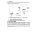
To program the number of Report Cycles: 1. 2. 3. From the Programming menu, select Communications, Accounts, Report Cycles [9518]. Enter a value between 01 and 03. Press when the desired setting is displayed. In the example illustrated in Figure 10.1, Account 1 is programmed with 2 call attempts, Account 2 is programmed with 3 call attempts and the number of report cycles programmed is 3. Figure 10.1: Typical Report Cycle Sequence 10.
3. The user presses 1 on their telephone; if there are additional events to report the next message is played. Otherwise, “No Further Messages” is announced. -orIf Two-Way Audio is enabled for the VM account, the user may open the audio channel by pressing 2 on their telephone. If the user does not want to open the audio channel they may press “@” then “#” on their telephone to hang up. The Vocal Message Dialer feature implements 3 call cycles when attempting to call the Vocal Message (VM) accounts.
10.3.4: Home ID The Home ID is a short message that is played at the beginning of a vocal message call in order to identify the system to the user. For example, at the beginning of the vocal message call, the message “Michael’s House” shall be played before the event messages. To play back the Home ID message: • From the Programming menu, select Communications, Accounts, Home ID, Play Message [95191]. To record a Home ID message: 1.
10.4.2: RP Passcode The RP passcode is a six-digit code that grants access to remote programming. When establishing an RP connection, the passcode programmed in the RP customer file on the PC must be identical to the system’s RP passcode. To edit the RP passcode: 1. From the Programming menu, select Communications, Remote Prog., RP Passcode [9522]. 2. Enter six digits. 3. Press when you have finished editing. 10.4.
2. 3. Enter up to 16 digits. Use the key to enter “*”, “#”, “,” (pause), “T” (switch to DTMF tone dialing), “P” (switch to pulse dialing) or “+” (international code). Use the key to delete one character at a time. Press when you have finished editing. 10.5.2: Service Call Interface For the Service Call feature, you can choose whether the system employs cellular or PSTN communication. To program the Service Call interface: 1.
10.6.3: First Test If the Periodic Test Interval is programmed as 001-254 hours, you must also program the time that the first Periodic Test is sent. To program the First Test Time: 1. From the Programming menu, select Communications, Comm. Options, First Test [95403]. 2. Enter a time (HH:MM). 3. Press when the desired setting is displayed. 10.6.4: Auto Interval The Auto Interval option determines the frequency of automatically calculated periodic test messages. To program the Auto Interval: 1.
10.6.8: Dial Tone Wait This option determines whether the system dials only when the dial tone is present or if the dialing is initiated regardless of the dial tone. To program the Dial Tone Wait option: 1. From the Programming menu, select Communications, Comm. Options, Dial Tone Wait [95408]. 2. Select Enabled or Disabled. 10.6.9: RDM Period Remote Diagnostics and Maintenance (RDM) session is a feature that is designed to enable automated maintenance of installed control systems.
To program the TWA mode option: 1. From the Programming menu, select Communications, Comm. Options, Two-Way Audio, TWA Mode [95412]. 2. Select Duplex or Simplex. 10.7: GSM Options 10.7.1: GSM RX Report The GSM RX Report is a feature that periodically reads the GSM signal strength of the Cellular Communications module – see 4.7.9: GSM Signal Strength. This reading occurs at the times programmed for the Periodic Test – see 10.6.2: Periodic Test Interval & 10.6.3: First Test.
10.7.3: SMS Center To edit the SMS Center telephone number: 1. From the Programming menu, select Communications, Comm. Options, GSM Options, SMS Center [954133]. 2. Enter up to 16 digits. Use the key to enter “*”, “#”, “,” (pause), “T” (switch to DTMF tone dialing), “P” (switch to pulse dialing) or “+” (international code). Use the key to delete one character at a time. 3. Press when you have finished editing. 10.7.
10.8: TWA Event Report Options 10.8.1: TWA Event Report The TWA Event Report is an event report that is sent to the central station to indicate that Two-Way Audio communication is about to commence. If enabled, the system sends the Contact ID event code 606000 before establishing Two-Way Audio communication. , This option affects Contact ID only. If using SIA, a TWA event report is always sent together with the TC/VM timeout, regardless of the configuration for this option.
10.9.2: Restore Reporting For each event group, you can determine whether restore messages shall be sent. To enable/disable restore reporting for an event group. 1. From the Programming menu, select Communications, Event Options [955]. 2. Select an event group. 3. From the event group’s sub-menu, select Report Restore [#2]. 4. Select Enabled or Disabled. 10.9.3: Two-Way Audio For Burglary, Fire and Medical event groups, there is an additional option that enables Two-Way Audio for that event group – see 5.2.
• • • o Transmitter Out of Synch. o Control system Transmitter Out of Synch. o Supervision Loss o Zone Trouble o FM Jamming Arm [#6] o Full Arm o Part Arm o Perimeter Arm Disarm [#7] o Disarm o Disarm after Alarm Water [#8] o Zone Water Alarm (Flood) To enable/disable the vocal message for an event group: 1. 2. 3. From the Programming menu, select Communications, VM Event Opt. [956]. Select an event group. Select Enabled or Disabled.
Chapter Eleven: Home Automation Programming This chapter explains the programmable options for the system’s home automation features. The Home Automation module is an add-on optional extra that you can install inside the control system’s plastic housing. 11.1: X10 Overview The control system’s home automation feature employs the X10 protocol and this enables compatibility with a wide variety of readily available home automation products.
11.2.2: On by Zone The On by Zone feature allows you to choose two zones that activate the HA unit when triggered. When either one of these zones is triggered, the system sends an On command to the HA unit according to the unit’s programmed Pulse Time – see 11.2.8: Pulse Time. For example, you have a magnetic contact installed above the front door. When the door is opened, the hall light is lit. To select the sensors that activate an HA unit: 1.
11.2.6: Telephone Control Via SMS or DTMF, you can send commands to the system in order to control various HA units. This option allows you to enable or disable this feature for each HA unit. To program the telephone control option for an HA unit: 1. From the Programming menu, select HA Programming, HA Units [961]. 2. Select an HA unit (01-16). 3. From the HA unit’s sub-menu, select TEL CTRL [#08]. 4. Select Enabled or Disabled. 11.2.
11.3: House Code The House code is part of the identification code of each HA unit. For the Home Automation features to function correctly, the House code on each HA unit must be identical to the House code programmed in the system’s memory. To program the system House code: 1. From the Programming menu, select HA Programming, House Code [962]. 2. Using the arrow keys, select a House code from the options available (A-P). 11.
Chapter Twelve: System Initialization The Initialization menu offers a number of options that enable you to reset the system. This menu is particularly useful when re-installing a control system at a new site. The Initialization function clears the entire system. This restores programming defaults, clears the log, user codes and the transmitter register. Options are also available that enable you to clear a specific section of the system’s memory separately. 12.
12.4: Clear Wireless Transmitters The Clear Wireless Transmitters function enables you to delete all registered transmitters at once. To clear the transmitter register: 1. From the Programming menu, select Initialize, Clear Wireless [974]; the system prompts you for confirmation. 2. Press to confirm; the transmitter register is cleared. 12.5: Find Modules The Find Modules function runs a diagnostic test that identifies the modules and keypads that are connected to the system bus.
Appendix A: Menu Structure Legend: Installer code required Master code required -86-
-87-
-88-
-89-
-90-
-91-
-92-
Appendix B: Transmitter Installation PIR Sensors (EL-2600/EL-2600PI/EL-2645/EL-2645PI) The EL-2600, EL-2600PI, EL-2645 and EL-2645PI are intelligent wireless PIR sensors for use with the infinite prime system. All of these sensors implement a feature to combat the problem of multiple transmissions, which drastically reduce the life of the batteries. After each transmission, there is a four-minute delay during which further transmissions will not be sent.
For maximum pet immunity the following guidelines are recommended: • Mount the center of the unit at a height of 2m with the PCB vertical setting at -4. • Set the pulse counter to 2. • Do not aim the detector at stairways that can be climbed by an animal. • Avoid a location where an animal can come within 1.8m of the detector by climbing on furniture, boxes or other objects. Installation Procedure To install PIR sensors: 1. Open the housing by removing the front cover.
Vertical Adjustment To position the PCB, turn the Easy Lock counter-clockwise and slide the PCB up or down to the required setting using the vertical adjustment scale. The detector’s coverage area is 14m x 14m (EL-2600/EL-2645) or 12m x 12m (EL-2600PI/EL-2645PI) when the PCB is positioned at 0. Slide the PCB up towards the -8 position to decrease the coverage area bringing the beams closer to the mounting wall.
Figure B.2: Lens Coverage Diagrams EL-2600/EL-2645 (left) and EL-2600PI/EL-2645PI (right) Magnetic Contact (EL-2601) The EL-2601 is a magnetic contact designed for installation on doors and windows. Antenna Installation Procedure To install magnetic contacts. LED Indicator 1. To open the housing, insert a small screwdriver at the bottom of the unit between the front and back cover and Battery twist the screwdriver to release the cover. Holder 2.
7. 8. 9. 10. 11. , 12. 13. To remove the PCB, press the PCB release tab and carefully lift the board and slide the board away from the back cover. The EL-2601 is able to operate in Jumper Position Operation Mode three modes: Magnetic Switch, Pins 1&2 Universal Transmitter Universal Transmitter or a combination Pins 2&3 Magnetic Switch of the two. If connecting a wired Jumper Magnetic Switch/ contact loop (N.C.), connect the Removed Universal Transmitter terminal block as follows: 1 - Alarm; 2 Table B.
5. 6. 7. , 8. 9. 10. 11. 12. 13. After registration, press the EL-2602’s tamper switch to terminate Test mode. Before permanently mounting the unit, test the transmitter from the exact mounting position. To remove the PCB, press the PCB release tab, carefully lift the board and slide the board away from the back cover. When handling the PCB, do not apply pressure on the antenna. Knockout the wiring hole in the back cover. Thread the wires through the wiring hole.
• • • Avoid installing in rooms with lined, insulating or sound deadening drapes. Avoid installing in rooms with closed wooden window shutters inside. Avoid installing in the corners of a room. The EL-2606 is best suited to rooms with moderate noise. , The sensor may not consistently detect cracks in the glass, bullets which break through the glass or glass breaking around corners and in other rooms. Glassbreak sensors should always be backed up by interior protection.
1. 2. 3. 4. 5. 6. 7. 8. 9. 10. 11. Open the housing using a small flat-head screwdriver to separate the base from the cover. Remove the insulator separating the battery from the contacts on the battery holder. When you apply power and the Tamper switch is open, the EL-2606 enters Test mode during which a transmission is sent every few seconds. You can terminate Test mode by closing the Tamper switch. Test mode is automatically terminated after approximately five minutes.
, 3. 4. 5. 6. , Each time the sensor generates an alarm, it also goes into Test mode for one minute. Hold the tester near the surface of the glass and aim the tester at the EL-2606. If drapes or blinds are present, test with the hand-held tester behind the closed drapes or blinds. Hold down the test button. When the LED on the sensor goes solid momentarily, the glass is within detection range.
6. 7. 8. 9. 10. Select the zone to which you want to register the transmitter; the system initiates Registration mode. When Save? appears on the control system’s LCD display, press . After registration, remove the Test jumper and place it over one pin for storage. Before permanently mounting the unit, test the transmitter from the exact mounting position. Attach the mounting base to the ceiling using the screws provided.
To replace the batteries: 1. Insert a small screwdriver into the pry-off slot – see Figure B.12 Carefully twist the screwdriver to separate the front and back of the casing. 2. Observing correct polarity, replace the batterie(s) (2 3V lithium, size: CR1225 for EL-2614 and 3V lithium, size CR2032 for EL-2614E).. 3. Close the casing making sure that the front and back click shut. Figure B.
9V Alkaline Battery Tamper Switch Buzzer Figure B.15: EL-2620 (back cover off) Battery Replacement (EL-2640) When the battery is low, the EL-2640’s LED flashes during transmission. To replace the battery: 1. Remove the battery cover located at the rear of the unit. To do so, press the release tab using a small screwdriver and lift the cover away from the EL-2640’s plastic housing. 2. Observing correct polarity, replace the battery (9V, alkaline). 3.
Transmitter Specifications The technical specifications for the transmitters that appear in this appendix are listed below. All transmitters are available in 868.35, 433.92 or 418MHz FM frequencies. EL-2600 Antenna: Built-in Whip Power: 3.
EL-2611 Antenna: Built-in Whip Power: Non-replaceable battery RFI Immunity: 40V/m Operating Temperature: 0 to 60°C Dimensions: 60 x 40 x 15mm EL-2614/EL-2614E Antenna: Built-in Whip Power: 2 x 3V Lithium Battery Size CR1225 (EL-2614) or 1 x 3v Lithium Size CR2032 (EL2614E) Current Consumption: 16mA, or 20 mA for EL-2614E(transmission) 2µA (standby) RFI Immunity: 40V/m Operating Temperature: 0 to 60°C Dimensions: 62 x 42 x 15mm EL-2620 Antenna: Printed on PCB Current Consumption: 26mA (transmission) 2µA (st
Appendix C: Event Table Burglary Description Restore Alarm from Zone Zone Alarm Restore Device Number NUB 1570 Device Number NUU 3570 Device Number NTA 1137 Device Number NTR 3137 Device Number NPA 1120 Device Number NPR 3120 Device Number NPA 1120 Device Number Tamper Duress Bell Cancel Device Number 3130 Panic Alarm Tamper Restore Address Field NBR Zone Panic Alarm Zone Panic Restore 1130 Zone Tamper Zone Tamper Restore Contact ID Zone Bypas
Power Description Restore Battery Low Battery Restore Address Field 1302 Device Number 3302 Device Number NXT 1384 Device Number NXR 3384 Device Number NAT 1301 Device Number NAR 3301 Device Number NLT 1351 Device Number NLR 3351 Device Number NET 1330 Device Number AC Loss AC Restore Contact ID NYR Transmitter Low Battery Transmitter Battery Restore SIA NYT Peripherals Media Loss Media Loss Restore Device Trouble Device Trouble Restore Transmitter Ou
Appendix D: Zone Types Normal A Normal zone is active when the system is armed. This zone generates a Burglary alarm instantly when triggered. Normal zones are designed for detectors installed inside the protected site or doors/windows that are never used to enter the premises. Event Group: Burglary Entry/Exit When the system is armed, Entry/Exit zones initiates the entry delay when triggered. If the system is not disarmed by the time the entry delay expires, a Burglary alarm is generated.
24Hr-X The 24Hr-X zone is a future option that is not available in the current firmware. Event Group: Not applicable Gas Gas zones are always active. In the event of a gas leak, these zones generate a Gas alarm. Gas zones are typically used with methane/propane/butane or carbon monoxide gas detectors. Gas alarms sound a distinctive siren pattern to easily distinguish them from other alarms. A gas alarm causes the siren to sound until the alarm is restored; the siren cut-off does not apply to gas alarms.
ELECTRONICS LINE 3000 Ltd. - LIMITED WARRANTY ELECTRONICS LINE 3000 Ltd. (hereafter “EL3K”) warrants its products to be free from manufacturing defects in materials and workmanship for (Wireless – 12 months excluding batteries, Control systems – 2 years, Dual Technology Detectors – 2 Years, PIR Detectors - 5 years) following the date of sale.
Copyright © 2008 Electronics Line 3000 Ltd. All rights reserved.