Synergy TRU-Balance BASIC OPERATION TRU-Balance 2INSTRUCTIONS Power2 RePower Tilt cline Removable Battery Pack ACN# 088 609 661
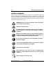
Basic Operation Instructions SAFETY GUIDELINES 2 WARNING! A Silver Star Provider or a qualified technician must perform the initial setup of this product and must perform all of the instructions in this manual. The symbols below are used throughout this owner's manual and on the product to identify warnings and important information. It is very important for you to read them and understand them completely. WARNING! Indicates a potentially hazardous condition/ situation.
TABLE OF CONTENTS Basic Operation Instructions 3 LABEL INFORMATION ................................................................. 4 INTRODUCTION ............................................................................ 6 INSTALLATION ............................................................................. 7 BATTERY PACK INSTALLATION TO EXTERIOR LIFT .................. 7 BATTERY PACK INSTALLATION TO BACKPACKER SERIES LIFTS ........................................................................
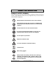
Basic Operation Instructions LABEL INFORMATION PRODUCT SAFETY SYMBOLS The symbols below are used on the product to identify warnings, mandatory actions, and prohibited actions. It is very important for you to read and understand them completely. Read and follow the information in the owner’s manual. Avoid exposure to rain, snow, ice, salt, or standing water whenever possible. Maintain and store in a clean and dry condition. Contact with tools can cause electrical shock.
LABEL INFORMATION Basic Operation Instructions 5 Disposal and recycling-Contact your authorized Pride Provider for information on proper disposal of your Pride product and its packaging. Battery charger for indoor use only. www.silverstarmobility.
Basic Operation Instructions INTRODUCTION WELCOME to Silver Star, a division of Pride Mobility Products Corporation (Pride). The product you have purchased combines state-of-the-art components with safety, comfort, and styling in mind. We are confident that the design features will provide you with the conveniences you expect during your daily activities. Understanding how to safely use and care for this product should bring you years of trouble-free operation and service.
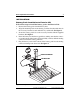
Basic Operation Instructions 7 INSTALLATION Battery Pack Installation to Exterior Lift Follow these steps to install the battery pack to the Exterior Lift: 1. Remove the battery pack from the battery base. 2. Align the mounting holes in the battery pack base bracket with those in the accessory bracket located under the key switch tube. See figure 1. 3. Secure the battery pack base to the accessory bracket with the supplied hardware. See figure 1. 4.
Basic Operation Instructions Battery Pack Installation to Backpacker Series Lifts Follow these steps to install the battery pack to a Backpacker Series Lift: 1. Remove the rubber caps and BATTERY PACK nuts from the protruding bolts on the side of the lift motor housing. See figure 2. LIFT MOTOR 2. Remove the spacer bar. See figHOUSING ure 2. 3. Mount the battery pack base onto the protruding bolts and secure into position with the nuts removed earlier. See figure 2. 4.
Basic Operation Instructions 9 PROHIBITED! Do not mount the battery pack in an area where it will be affected by moisture or dirt. Follow these steps to install the battery pack to the SilverBoom: 1. Determine a location to mount the battery pack to the vehicle. See figure 3. 2. Inspect the undercarriage of the vehicle (where the battery pack is located) for obstructions that may hinder the installation of the mounting screws that secure the base to the vehicle (e.g.
Basic Operation Instructions BATTERY CHARGING Batteries may encounter temperature extremes that can influence their performance. Extreme heat diminishes the charge on the battery; extreme cold slows the available power and extends the time needed to recharge the battery. Keep the batteries fully charged whenever possible and protect the batteries from extreme heat or cold. WARNING! Always protect the batteries from freezing and never charge a frozen battery.
Basic Operation Instructions 11 In House Docking Station Charging Follow these steps to charge the battery pack with the In House Docking Station: 1. Remove the battery pack from the battery pack base. 2. Place the charger base near a standard electrical outlet. See figure 4. 3. Connect the charger harness to the power lead extending from the charger base, then plug the 3-pronged plug into the electrical outlet. 4. Place the battery pack onto the charger base. 5.
Basic Operation Instructions Backpacker Series/SilverBoom Battery Pack Charging The battery pack used on the Backpacker Series and SilverBoom is a self-contained unit, which includes 1 battery and an internal battery charger. The battery pack charger is designed to charge the lift battery and those of a mobility product, switching between the 12-volt lift battery and the 24-volt mobility product batteries, depending on which battery is in need of a charge.
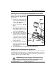
Basic Operation Instructions 13 Mobility Product Battery Charging The battery pack’s internal charger is capable of charging the batteries of the mobility product you are transporting. This option is only available for Backpacker Series and SilverBoom lifts. The internal battery pack is also capable of PLUG INTO charging a 24-volt mobility product AUXILIARY equipped with a compatible Neutrik OUTLET NC3MXX connector (for pin Figure 6. Charging A Mobility Device configurations, see figure 7).
Basic Operation Instructions BATTERY REPLACEMENT MANDATORY! Battery posts, terminals, and related accessories contain lead and lead compounds. Wear goggles and gloves when handling batteries and wash hands after handling. WARNING! Always replace the battery with the exact same type, chemistry, and amp-hour (Ah) capacity. Refer to the specifications table in this manual for recommended type and capacities. To remove the battery from the pack (see figure 9): 1. Remove the battery pack from the base. 2.
Basic Operation Instructions 15 TROUBLESHOOTING Any electromechanical device occasionally requires some troubleshooting. However, most of the problems that may arise can usually be solved with a bit of thought and common sense. Many of these problems occur because the battery is not fully charged or because the battery is worn down and can no longer hold a charge. What if the battery will not charge? Fully insert the appropriate ends of the charger cord into their ports.
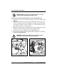
Basic Operation Instructions In the event the battery pack’s fuse should cease to work: 1. Remove the fuse by pulling it out of its slot. The fuses are located on the underside of the battery pack. 2. Examine the fuse to be sure it is blown. See figures 12 and 13. 3. Insert a new fuse of the proper rating. Figure 12. Working Fuse Figure 13. Blown Fuse (Replace) WARNING! The replacement fuses must exactly match the rating of the old fuses.
Basic Operation Instructions 17 CHARGER SPECIFICATIONS LED Operating Vehicle Voltage Operating Input Voltage Input Current (RMS): Input Fuse Output Fuse (One For Each Battery) Car Voltage minimum for auto shut-off Maximum Charging Current Onboard LEDs: (2) One For Each Battery CONDITION 12.1V - 15.5V DC (Measured at car battery) 11.5V - 15.5V DC (Measured at charger) 5.8 Amps maximum 3AG 7-Amp or ATC 7.5-Amp (Fast Blow) 4-amp (Fast Blow) 12.1-Volts 2.5-Amps Color: green www.silverstarmobility.
Removable Battery Pack Basic Operation Instructions www.silverstarmobility.
Basic Operation Instructions www.silverstarmobility.
Pride Mobility Products Corporation 182 Susquehanna Avenue Exeter, PA 18643-2694 USA Pride Mobility Products Company 380 Vansickle Road Unit 350 St. Catharines, Ontario L2R 6P7 Canada www.pridemobility.com www.silverstarmobility.