
Owner`s manual


Quantum Dynamo ATS RevE/May03 www.pridemobility.com 19
OPERATION
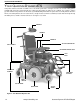
Figure 14. Anti-Tip Wheel Adjustment
LOOSEN THE NUT AND BOLT
REMOVE THE
ANTI-TIP WHEEL
ANTI-TIP WHEEL ADJUSTMENT
You can adjust the anti-tip wheels so that they are higher or lower. Ad-
justing the anti-tip wheels also affects the stiffness of the suspension.
Raising the anti-tip wheels stiffens the suspension while lowering the
anti-tip wheels softens the suspension.
To adjust the anti-tips:
1. Make sure the power chair is not in freewheel mode.
2. Use a 5/32-in. hex key and a 7/16-in. socket to loosen the nut and
bolt that fasten the anti-tip spring to the anti-tip arm. See figure 14.
3. Use a 1/2-in. wrench and 1/2-in. socket to remove the anti-tip wheel.
4. Use a 5/32-in. hex key and 7/16-in. socket to remove the anti-tip
adjustment bolt.
5. Raise or lower the anti-tip wheel in 1/4-in. increments.
6. Replace the hardware into the appropriate holes and tighten.
7. Install the anti-tip wheel.
REMOTE PLUS CONTROLLER
The electronic controller is what you use to operate your power chair. It takes the battery voltage and sends it to the appropri-
ate system. The electronic controller also enables you to monitor battery charge, electronic controller functions, and the
condition of your electrical system. Also, it may be used to control some optional systems such as power elevating seats and
lights.
The Remote Plus is a modular electronic control system. The electronics necessary to operate the power chair are contained
in several modules located on different parts of your power chair.
The Remote Plus system consists of the following components:
n master remote
n communications cable(s)
n power module
n motor wiring harnesses
n battery wiring harnesses
n actuator lighting module (for optional equipment)
The master remote is located typically on the end of an arm-
rest. The other components are located inside the power
base.
Remote Plus Master Remote
The Remote Plus master remote consists of the following
(see figure 14a):
1. joystick
2. keypad
3. controller communications cable
4. off-board charger/programming socket
Joystick
The joystick controls the direction and speed of your power chair. When you move the joystick from the neutral (center)
position, the electromagnetic brakes release and allow your power chair to move. The further you push the joystick from its
neutral position, the faster your power chair moves. When you release the joystick and allow it to return to the neutral position,
you engage the electromagnetic brakes. This causes your power chair to decelerate and come to a complete stop.
1
2
3
4
Figure 14a. Remote Plus Master Remote
OPERATION