SOFTWARE VERSION 3.6.1 WWW.PRG.
AutoPar®, Bad Boy®, Best Boy 4000®, PRG Series 400®, MBOX®, MBOX Extreme®, OHM™, Super Node™, V476®, V676®, Virtuoso®, Virtuoso® DX, Virtuoso® DX2, and VL6C+™ are trademarks of Production Resource Group, LLC, registered in the U.S. and other countries. Mac®, QuickTime® and FireWire® are registered trademarks of Apple Computer, Inc. All other brand names which may be mentioned in this manual are trademarks or registered trademarks of their respective companies.
TABLE OF CONTENTS Introduction About This Manual........................................................................................................................................................................ Important Note About Consoles!.................................................................................................................................................. Additional Documentation .............................................................................................
Chapter 3. Operation Media Content File Type Specifications .............................................................................................................................................................. Recommended Practices ........................................................................................................................................................... Media Content Management ..........................................................................................
Stripe Ring (002/006)........................................................................................................................................................... Fisheye (002/007) ................................................................................................................................................................ CylinderScreen (002/008)....................................................................................................................................
Chapter 7. Content Creation and Utilities Creating Custom Content Creating Movies and Audio Files .............................................................................................................................................. File Extension .................................................................................................................................................................... Codec .....................................................................................
REVISION HISTORY This manual has been revised as follows: Version Release Date Notes 02.9800.0001.36 January 8, 2013 Initial release. 02.9800.0001.36 A May 22, 2013 Updated to software version 3.6.
Notes VIII MBOX® MEDIA SERVER USER MANUAL
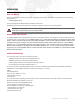
INTRODUCTION About This Manual This manual provides necessary information regarding product safety, installation, and operation for the following PRG product: + MBOX® Media Server This manual applies to MBOX Designer software version 3.6.1. Familiarizing yourself with this information will help you get the most out of your PRG product. WARNING: It is important to read ALL accompanying safety and installation instructions to avoid damage to the product and potential injury to yourself or others.
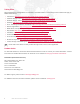
Training Videos Mbox Media Server Training Videos are available on the PRG website. The following is a list of videos that apply to MBOX Media Server: + Introduction: http://www.prg.com/mbox-media-server-training-video-1/ + Hardware Set Up- Front: http://www.prg.com/mbox-media-server-training-video-2/ + Hardware Set Up - Rear: http://www.prg.com/mbox-media-server-training-video-3/ + Patching: http://www.prg.com/mbox-media-server-training-video-4/ + CITP - Streaming Feedback & Thumbnails: http://www.prg.
1. OVERVIEW This chapter provides an overview of MBOX features, components, and operations.
GENERAL OVERVIEW Important Terminology When discussing the MBOX Media Server, it is important to understand the terminology which distinguishes the hardware components from the software. These concepts are as follows: + "MBOX Designer" refers to the software. + "MBOX EXTREME" or "MBOX EXTREME server" refers to the rental hardware which runs the MBOX Designer software. + The term "MBOX" may refer generically to one or both.
Feature List + Single-server rack with integrated UPS, I/O module, and Auxiliary Input panel. * + Digital Dual I/O Module with built-in DMX-to-Art-Net conversion and Ethernet switch. VGA (RGBHV), DVI, and SDI (SD/HD) stage outputs, DVI preview output. * + Dual video output per server with multiple operating modes: Single Output, Dual Independent, Panoramic Wide, and Panoramic Dual. + Accepts live video input SDI (HD/SD), composite and FireWire® (DV). + 1080p HD Video playback. + Movable camera viewpoint.
Concepts of Operation Basic Function The basic function of the MBOX Designer software is to control dynamic media - such as movie clips, still images and 3D objects - during a stage show or other performance. The resulting visual imagery is output to a display device such as a projector, LED wall, plasma screen or low-res LED lighting fixture. Built-in features allow the media to be manipulated "on the fly" so that changes can be made during the actual performance and immediately projected.
COMPONENTS Note: This section deals with MBOX EXTREME hardware and may not be pertinent to a computer-only installation.
Dual I/O Module The function of the Dual I/O module is to provide video conversion, final dimming of the video signal, and to send EDID information to the Mac computer. The module also handles DMX512 and Art-Net input for the computer. The module functions as a "dual" unit since it provides two independent output sections. These sections are noted in the drawing below as "Server Output 1" and "Server Output 2." Note: This is intended to be an overview of the Dual I/O module components.
DMX Input Ports - The DMX512 XLR ports are used to receive DMX512 data from an external console or other controller. The left DMX512 port is automatically configured as Art-Net universe 0, while the right DMX512 port is configured as Art-Net universe 1. (DMX512 cables can only carry one universe of data at a time, and in some cases the MBOX Designer software requires two universes.
Auxiliary Input Panel The Auxiliary Input panel provides input/output connectors for signals other than video and DMX/Art-Net. + Ethernet - This port is used when networking multiple MBOX EXTREME servers together. + Audio Out - The XLR audio outputs are balanced. The mini plug audio output is unbalanced. + SMPTE In - The SMPTE input will accept balanced or unbalanced signals. + MIDI In/Out - The MIDI input currently accepts MIDI timecode.
Mac Computer The MBOX EXTREME Media Server contains a Mac Pro computer which has been customized by PRG. The Mac computer is used to operate the MBOX system and store the media. It also provides standard computer connectors such as USB and FireWire® for the purpose of importing or exporting media data. + Hard Drives - The Mac computer contains four hard drives: one which is used to boot the system, and three which are arranged in a striped raid array (treating them as a single drive).
The v3.5 MBOX EXTREME rack contains upgraded and new components as shown below: Mac Rear Detail (v3.5) optical in audio out 1 2 Ethernet Card (v3.5 only) USB Ethernet FireWire Audio SPDIF Audio In/Out Video Capture Card (upgraded in v3.5) Genlock Card Graphics Card Figure 1-7: MBOX EXTREME v3.5 Components Note: Version 3.5 racks can be easily identified by the "v3.5" label on the top of the MBOX EXTREME rack case.
FIXTURE DESCRIPTIONS MBOX Environment Concept In order to get the most from MBOX Designer, it is important to understand the overall concept of the MBOX environment, which is essentially a building platform for "virtual scenery." The final "look" of this virtual scenery is comprised of multiple layers. These layers can be made up of backgrounds, 3D objects, camera angles, and lighting, all of which are controllable elements within the MBOX environment.
Fixture and Layer Overview The MBOX environment is based on the concept of layers. The system supports up to 12 active layers at a time, each having its own particular elements and parameters. The elements include a choice of still images, movies, or 3D objects. The parameters include settings such as opacity, texture, intensity, color, blending, rotation, and many more. The combination of all 12 layers results in the final "look" of the virtual scenery.
LAYERS Fixture: Texture (2D) + Effect 1 with Controls A & B + Effect 2 with Controls A & B + (Opacity + Color: Red, Green, Blue + Texture Folder Number + Texture File Number + Playmode and Playspeed + In-Frame + Out-Frame + Sync Stream and Sync Offset (Timecode and Layer-to-Layer) + Aspect Ratio + Frame Blending + Crossfade Type and Timing + X, Y, and Z Positions + Scale Fixture: Objects (3D) + X, Y, Z Rotation, Spin, and Scale + Object Folder Number + Object File Number + Animation Speed + Animation 1 and
Fixture, Layer and Parameter Details Ambient Light and Spot Lights 1 - 4 The Ambient and Spotlight fixtures are used to light 3D objects or digital gobos and have no effect upon textures used as backgrounds. Each lighting fixture has an intensity parameter along with color controls for red, green and blue. Guidelines: + If no lights are turned on (i.e., have an intensity level above 0), then the 3D objects will not be visible on the screen.
Guidelines: + The keystone adjustments act upon the composite image created by the 12 content layers. Layers: Texture + Object Each of the 12 content layers incorporates both Texture (2D) and Object (3D) functionality. The Texture element displays still images and movies as backgrounds. The Object element displays 3D objects or digital gobos. The combination of the Texture and Object elements make up the final composition of each layer.
OPERATING MODES MBOX Designer v3.6 Modes MBOX Designer v3.6 has four modes of operation: Single Output, Dual Independent, Panoramic Wide and Panoramic Dual. The primary purpose of the operating modes is to configure the screen arrangement and required Art-Net universes. The MBOX Setup tab, covered later in this manual, is used to change the operating mode. (Refer to "Setup" on page 43).
Panoramic Wide Mode The Panoramic Wide mode provides two video outputs from the software. The two outputs create a single display surface and the overlap and blending between the two outputs can be adjusted. Outputs can be arranged either horizontally or vertically. The two outputs share one set of lighting, camera, shutter, and keystone fixtures. Any of the software's 12 possible content layers can be displayed on either screen or across the overlap with a portion on each screen.
Notes 20 MBOX® MEDIA SERVER USER MANUAL
2. INSTALLATION AND POWER-UP This chapter provides instructions for setting up the MBOX server and powering up for the first time.
SAMPLE CONFIGURATION DIAGRAMS Overview There are many possible configurations for setting up single or multiple MBOX EXTREME servers. The following illustrations show just a few of the many possibilities. While the example details the use of the MBOX EXTREME server rack and its included Dual I/O Module, the same examples can be applied to a computer running the MBOX Designer software.
Art-Net Input Configuration: Network Switch and Multiple Media Servers In the following configuration, Art-Net control signal is distributed from one control console to one network switch. The network switch then distributes the control signal to all MBOX EXTREME servers.
Output Configuration: Single Media Server with Plasma Display and LCD Projector In the following configuration, a Plasma Display and LCD Projector are connected to a single MBOX EXTREME server.
SETUP Basic Setup and Connections To interconnect the case components: Step 1. Remove front and back covers from case (Figure 2-4). Step 2. Remove keyboard and trackball from case. Step 3. At rear of case, verify that Monitor (2), USB (3), Ethernet (2), Video In (2) and Power cables are connected to computer.
Connecting the Stage Output The stage output should be connected to one of the outputs ports on the front of Dual I/O module. This will vary depending on the type of output device. (Refer back to "Dual I/O Module" on page 8.) Guidelines: + Adapters or converters may be required to convert these outputs to specific needs. + All DVI connectors on the Dual I/O module are DVI-D (digital only). There is no analog signal present on these connectors, therefore, a DVI-to-VGA adapter will not work.
GETTING STARTED Power-Up Overview When an MBOX server is powered up, it will typically launch the MBOX Designer application. (If for some reason the application does not start automatically, locate the MBOX Designer icon on the Apple® dock and click once). When launched, the MBOX Designer software will initially show a splash screen. After a brief pause, the application window will appear. During this time the software will scan and index all media.
Power-Up Procedure Use the following procedure to power up the MBOX EXTREME server. Step 1. Ensure UPS is powered up. Step 2. At front of rack, press Mac computer power button (Figure 2-6) and allow computer to boot. Step 3. Press power button of any connected preview monitors. Step 4. Allow MBOX DEISGNER software to launch. (The software should start automatically. If it does not start automatically, click on the icon in the dock.
PATCHING FIXTURES Patching Overview In order to control MBOX, it will need to be "patched" to a control console. Patching allows channels to be mapped to the controllable elements of the MBOX environment. Use the following guidelines when patching: + One MBOX server running MBOX Designer v3.6 software requires at least 466 DMX512 channels. + At least one DMX512 universe per server is required for Single Output, Panoramic Wide, and Panoramic Dual modes.
Parameter Mapping All 16-bit values are in Big Endian format. For example, the value 23 would be presented as 0 in the first channel and 23 in the second channel.
Summary: Dual Output - Panoramic Wide Start Size Type 1 4 5 Summary: Dual Output - Panoramic Dual Universe Start Size Type Ambient Light 1 4 Ambient Light 4 Spot Light 1 5 4 Spot Light 1 9 4 Spot Light 2 9 4 Spot Light 2 13 4 Spot Light 3 13 4 Spot Light 3 17 4 Spot Light 4 17 4 Spot Light 4 21 32 Camera Control 21 32 Camera Control 53 20 Shutter Control 53 20 Shutter Control 1 73 22 Keystone Control 1 95 20 Shutter Control 2 1st 466 Total Channels 73
Summary: Dual Output - Independent (Universe Offset +0) Summary: Dual Output - Independent (Universe Offset +1) Start Size Type Start Size Type 1 4 Ambient Light 1 4 Ambient Light 5 4 Spot Light 1 5 4 Spot Light 1 9 4 Spot Light 2 9 4 Spot Light 2 13 4 Spot Light 3 13 4 Spot Light 3 17 4 Spot Light 4 17 4 Spot Light 4 21 32 Camera Control 21 32 Camera Control 53 20 Shutter Control 53 20 Shutter Control 73 22 Keystone Control 73 22 Keystone Control 95
Playing Back Video - Quick Start Once a console has been connected, the MBOX fixtures patched, and the display device turned on, video can be played back. To immediately play back video: Step 1. At console, select Camera fixture and set its intensity to full. Very Important! – the Camera fixture’s intensity controls the built-in hardware dimmer on the I/O module. If this channel is at 0, there will be no output from the stage outputs on the I/O module – though there will be output on the preview outputs.
Step 4. At this point, adjust the folder and file parameters to scan the stock media content. For example, changing to Texture Folder 11,Texture File 1 will result in the following clip: Step 5. To apply an effect to the layer, for example, set the Effect 1 parameter to 2 (sepia tone) and set the Effect 1 Control A to 255 (full).
3. OPERATION This chapter provides instructions for configuration and operation of the MBOX server.
MEDIA CONTENT File Type Specifications The MBOX server supports Apple QuickTime® technology for rendering and playback of images and movie files. The following file types are supported: Still Image Files JPEG (.jpeg or .jpg), PNG (.png), TARGA (.tga), TIFF (.tiff or .tif) for still image files. + For still images not requiring transparency, JPEG is the best choice. + To use files with transparency, PNG is the best choice. Movie Files QuickTime format (.mov) for movie files.
Typically, movie files should not have embedded audio tracks, although embedded audio tracks in movies can be made to play. To remove audio tracks from movies, use your preferred application to re-render or export the movie without its audio tracks or try dropping the file onto the MBOX File Converter application, making sure the "copy audio" checkbox is not checked (see "MBOX File Converter" on page 130). If the file extension of a DV movie file is changed from .mov to .
At startup, the MBOX Designer software performs a media scan to search all folders that reside within the Mbox/ Media and Mbox/Models folders on the MBOX server’s RAID. External media can be attached to these folders using aliases, provided the following guidelines are observed: + Aliases must link to folders on the supplemental media. They cannot be aliased to files. + An alias cannot refer to another alias. + The /Mbox/Media, and /Mbox/Models folders cannot be aliases.
Folder 000 in both the Media and Models folders is reserved and should not be used. The stock PRG movies and still images are located in Media folders 001 - 038 and 248 - 254. Media folder 255 is reserved for video inputs and layer copy functionality. The stock PRG 3D objects, animated gobos, and digital gobo files are located in Model folders 001 - 006. CAUTION! File names (after the numerical prefix) should not start with numbers, as this confuses the media indexing. For example, a file name such as 001.
Adding Media Content When adding content files, it is recommended that new, unique folder numbers be created for the custom content. It is possible to have more than one folder with the same numerical prefix, however, as long as the content files within such folders do not have the same numerical prefix. CAUTION! Numbered content files will be assigned a folder number that is equal to the numerical prefix of their immediate parent folder. Therefore, using folders without numbers requires caution.
Creating and Viewing Content Thumbnails The MBOX Designer software will create thumbnail images of the content. To force the creation of new thumbnails in MBOX Designer, press [ T]. Thumbnail images are stored in a standard location on every server and are grouped with HTML files that allow any networked computer (Mac or PC) to use an HTML browser to view the thumbnails on the server. Individual thumbnails can also be used by consoles connected to the server.
APPLICATION WINDOW Overview The MBOX Designer application window allows the server’s output to be viewed in either Window or Fullscreen mode on the preview monitor. Fullscreen - While in Fullscreen mode, the server’s output (i.e., video) will be displayed at "full screen" without any user interface showing. In this mode, the output will also be visible on the Stage output of the Dual I/O module. Window - While in Window mode, the application’s user interface will be displayed.
Setup The Setup tab of the MBOX Designer application window is used to: + Set the operating mode and Art-Net universe for the MBOX server. + Set the application to start in either Window or Fullscreen mode. For Window mode, the window size can be set. For Fullscreen mode, the resolution can be set. + Input License Key to authorize the application. + Set a width and height for Textures.
Setup: Control The Control section is used to set the operating mode, protocol, address and layer count for the server. + Mode - use this pop-up menu to select the desired mode. (Refer to "Operating Modes" on page 18 for detailed information about each mode.) It is important that the operating mode match the console profile that is being used.
Setup: Fullscreen Mode The Fullscreen Mode section is used to set the native resolution, frequency, and aspect ratio of the stage display device being used. It is not uncommon to change the Fullscreen Mode settings since, for example, a standard definition projector would require different settings than an HD projector, etc. Getting the desired results from any Fullscreen mode setting requires the computer to be receiving EDID information that matches the Fullscreen mode settings.
Note: The EDID from the MBOX Dual I/O Module provides EDID with accuracy to two decimal places (e.g., 59.94Hz). However, the Mac Displays Preference window rounds these frequencies to no decimal places (e.g., 60Hz). Functionally, MBOX Designer is still able to request and receive the correct frequency when entering Fullscreen mode, but it is difficult and confusing to set the desktop to the same frequency.
Setup: License The License section is used to enter a license key, as required. A rental MBOX EXTREME server should already be licensed before shipping, however, even without a valid license key, the MBOX Designer software will be licensed as long as a Dual I/O module remains connected to the computer via USB. If the software is unlicensed and no I/O module is connected, then the video output will be watermarked and the application will quit automatically after 30 minutes of use..
Setup: Network The Network section is used to configure the Sync and CITP settings when connecting two or more MBOX servers. + Sync - sets which port the server will use for layer-to-layer and network timecode sync. + CITP - selects the port that the MBOX Daemon application uses for communication. When changes are made here, it will be reflected 4-5 seconds later in the Daemon screen. (Refer to "MBOX Daemon" on page 28 for more information.
Setup: Options The Options section is used to enable/disable various software features. + No Diagnostics - Checking this box will disable the MBOX Designer automatic error-reporting images such as the icons for locked content, broken movie, etc. (Checking this box is recommended during show situations). + Deinterlace Video Inputs - Checking this box will cause MBOX Designer to deinterlace the video signal that it receives on the local video inputs, resulting in better rendering.
HEADS UP DISPLAYS (HUDS) Overview MBOX Designer provides Heads Up Displays (HUDs) that contain detailed information about the server. There are two methods for calling up most of these HUDs: the Camera fixture control channel or the keyboard. Refer to the chart on page 154 for a listing of discrete values for the Camera Control Channel.
Using the HUDs The HUDs can be very useful during programming to view the values for fixtures and parameters. When making changes to the parameters, the values will be immediately reflected in HUD screens. For example, when making changes to parameters on the Layer 1 Fixture, they can be viewed in the Layer:Texture HUD (F2). The following screen shows Layer 1 with the default levels: This next screen shows Layer 1 after some modifications have been made to the effects, color and scale.
DUAL I/O MODULE Operation Overview Note: For an overview of Dual I/O module components, refer back to "Dual I/O Module" on page 8. The function of the Dual I/O module is to provide video conversion, final dimming of the video signal, and to send EDID information to the Mac computer. The module also handles DMX512 and Art-Net input for the computer.
Connected Display Devices and EDID Overview Without special hardware or software, a typical computer can only output video resolutions and frequencies that are supported by the display equipment that is connected to it. Display devices communicate their required input configurations via EDID (Extended Display Identification Data), which is essentially a communication protocol used between a device and a computer.
Switching Between Modes The MBOX server can operate in one of three default EDID settings, or, if the default sets are not appropriate for the connected display devices, then a custom EDID setting may be captured. Default EDID Sets - Three default sets of EDID data stored within the Dual I/O module provide the necessary information to work with standard computer display resolutions and frequencies, and typical SD and HD-SDI resolutions and frequencies.
Switching Between Standard EDID or Capturing EDID The EDID set can be changed using the Stage Blackout and Preview Dim switches located on the front of the I/O module. The combination of these switch settings (as either Yes or No) will determine the default EDID set - or, if a custom EDID will be captured - when the EDID Capture switch is engaged. To switch between the three standard EDID sets: Step 1.
Step 8. After four seconds, the LED will stop flashing and will remain on for about two seconds. During this time the EDID data is being captured. Step 9. Once the external capture is complete, the LED will again flash, but more slowly than before. At this point, release the switch. Step 10. At Mac Displays Preference window, click Detect Displays button. The computer will re-sync the outputs and the new EDID will be applied. (You can connect your display devices at this point.) Step 11.
SDI Output (SD - Standard Definition & HD - High Definition) IMPORTANT! This requires connection to a Dual I/O Module. If you are using MBOX Designer without the Dual I/O Module, you will not be able to output SDI. The MBOX Designer software supports SD/HD-SDI output directly from the Dual I/O module without need for a scan converter. SDI can be sent from both outputs of the I/O module simultaneously.
Example - To get MBOX to output 720p/59.94Hz, do the following: Step 1. Open Mac Displays Preference window. Step 2. Using switch combinations outlined on page 56, change EDID set on both outputs of the I/O module to the PRG-MbE 59.94Hz set. Step 3. At Displays Preference window, click Detect Displays button. Reset desktop resolution/frequency of both displays to 1280 x 720 and 59.94Hz. Step 4. At MBOX Setup tab Fullscreen mode section, select "HD-SDI 720p59.94" in pop-up menu.
The MBOX Genlock feature uses an additional connection between the rear of the I/O module and the Genlock card in the Mac computer. This card is located next to the Graphics card and has two LED indicators - one red and one green - which function as follows: optical in audio out 2 + When the card is receiving data (i.e. when a genlock input is connected to the I/O module), the red LED will turn off and the green LED will turn on. 1 + If the card is receiving power but no data, the red LED will turn on.
ENHANCING MBOX PERFORMANCE Recommended Practices Use the following recommended practices to enhance the performance of your MBOX system: + Disable any screen-savers. + Disable File Sharing and Remote Management (any and all sharing, in fact). + Turn off automatic software updates. + Disable Spotlight on all connected hard-drives by placing them in the Privacy table. + Set Energy Saver settings to disable computer and display sleep, and to stop hard-drives from being put to sleep.
4. ADVANCED FEATURES This chapter provides instructions for using the advanced features of the MBOX Designer software.
3D OBJECTS AND DIGITAL GOBOS About 3D Models and Digital Gobos (Objects) 3D Model and Digital Gobo files are arranged into individual folders within the /Mbox/Models folder. Lighting All 3D models and digital gobos require some amount of lighting to be properly visible. If the object file is used without turning on one of the MBOX lighting fixtures or without using Drawmode 1 (Light), then the object will appear on the screen as a black silhouette.
All appropriate files in the Models folder will be compiled automatically the first time MBOX Designer is started (and successfully locates them). Thereafter, files in the Models folder will only be compiled if they are new or if they have been modified since the last time MBOX Designer was used. Compiling all of the stock files in the Models folder takes some time, but this task only needs to happen once in the background, allowing all other functions to be available during this process.
If you create an object that is scaled to match a particular piece of 2D content (which is measured in pixels), and you want MBOX to treat generic units as pixels, add the suffix ".pixels" to the file's name before it is compiled. Example: a file named - 001.NewObject.obj should be renamed as - 001.NewObject.pixels.obj In this case, an object that is 200 generic units tall will appear as 200 pixels tall within MBOX. And a piece of 2D content that is 200px high would fit exactly when applied to that object.
Creating Custom Digital Gobos Overview Custom digital gobos can be created in two formats: SVG and AI (Adobe Illustrator®). Adobe Illustrator is the best application for creating custom digital gobos because it provides the best toolset for features that MBOX Designer supports. SVG files are the most compatible and they provide better functionality than AI files. MBOX Designer's vertex array compiler pays attention to "object fill" information in these file types.
Step 2. Use the various drawing tools to compose the gobo. The most useful tools are the objects (ellipse, rectangle, polygon, or star), the paintbrush, the linear tools (line, arc, spiral), text tool, and the pencil. All of these tools, except the line tool, will create a filled object. Filled objects will be compiled as solid areas in MBOX and will be the areas that accept a texture, if one is applied. Text Lines Objects Paint Brush Pencil Tool Options Step 3.
Step 4. To expand an object, first select the object, then choose Expand from the Object menu. This will open a pop-up window. You don't need to change any of the options in the window, just press OK. Add more objects as desired. (You can use multiple layers, if required.) Step 5. Use the text tool to create text as desired. Use the Character options to set font and size.
Step 6. Text is a special case, and must be converted out "outlines." Switch to the Selection Tool and select the text. Select "Type" in the menu bar, and then select "Create Outlines." You cannot make outlined text (stroke only), it has to be filled. Step 7. If you are creating an SVG gobo, you need to apply a crop area to the document. The size and location of this crop area will determine whether your digital gobo will fall under Option 1 or Option 2.
Step 8. Before you saving the file, consider where the center of the file should be. By default, the center of a digital gobo will appear in the center of the MBOX Designer window and the gobo will rotate around that center point. If you save the file as an AI file, you can set the center by modifying the origin of the file in Illustrator.
Animated Digital Gobos MBOX animated gobos are similar to SVG gobos, but they have built-in functions which have their own controls. Animated gobos, saved as .dgob files, are located in the /Mbox/Models/002.Animated_Gobos folder. Unlike normal digital gobos, these files do not need to be compiled so there will be no corresponding .vtxa files. Like other digital gobos, the animated gobos are treated as objects and some of them require lighting.
TV Screen v1.4 (002/001) The TV Screen animated gobo allows a texture to be placed onto a plane in 3D space and manipulated it as a 3D object. The texture can rotate and spin on all three X, Y, and Z axes. (A texture on its own will only rotate on the Z axis.) The TV Screen will automatically light itself and Drawmode 1 does not have to be set for it to be visible.
Snow v1.2 (002/002) The Snow animated gobo is somewhat complicated. In order to have complex snowflake shapes, a folder named "snowflakes" must be created within the Mbox folder and numbered .vtxa files (1 to 254) must be placed into it. .vxta files can be copied from the model_cache folder into the snowflakes folder. In the example below, the left-hand image shows the default (000) snowflake shape: a round flake. The right-hand image shows several different flake shapes: the shape is set to random (255).
Tunnel v1.1 (002/003) The Tunnel animated gobo is a virtual tunnel made up of rings. The shape can be rotated. Animation Speed controls the rate and direction in which the rings move. + The A modifier controls the number of rings. + The B modifier controls the thickness of the rings. In the following example, the X and Y rotation has been adjusted so that the shape can be seen more clearly. The Tunnel’s default position is directly head-on to the camera. Flag v1.
Ring Stripe (002/005) For the Ring Stripe animated gobo, Animation Speed controls the scale. + The A modifier sets the segment thickness. + The B modifier sets the number of segments (= value +1). Stripe Ring (002/006) For the Stripe Ring animated gobo, Animation Speed controls the central diameter. + The A modifier sets the line thickness. + The B modifier sets the number of lines (= value +1).
CylinderScreen (002/008) The Cylinder Screen animated gobo provides a similar surface to the TV Screen gobo that can also bend around its Yaxis. Animation speed (default = 127) controls the amount of the curved surface that is covered by the texture applied to the layer. Adjusting this control makes it look like the texture is being scaled up and down, however, notice that the apparent curvature of the texture changes as it fills more of the curved surface.
Fit To Screen (002/010) The Fit To Screen animated gobo can be used to force any content to fill the screen in one of three ways: Horizontal, Vertical, Horizontal & Vertical. The layer's scale parameter must be at their default values for the fill to work correctly. The FIt To Screen gobo requires no lighting. The A modifier selects the fill mode: + 0 - 63: Image is scaled so both width and height are >= screen size (i.e.
ANIMATED TEXTURES Using Animated Textures (Animations) Animated Textures are found in folder 248 of the Media folder. They are similar to the Animated Gobos in the Models folder, but are controlled differently and cannot have a texture (movie, still image, etc.) applied to them. Each animated texture has white areas and transparent areas. The white areas can be colored using the RGB controls on the layer.
LAYER COPY Using Layer Copy At times, there may be a need to play the same movie content on more than one layer at the same time. The same content can be requested on multiple layers, but doing so causes the content to be read from the hard-drive more than once, as well as being decompressed more than once. This is a waste of resources if you intend to display the same frame of the same movie on multiple layers at the same time.
DRAWMODES Using Drawmodes The Drawmodes feature provides control over how a 3D object is lit and how it interacts with other layers. Drawmode has its own control channel with several modes.
Drawmode 16 - Orthographic View Drawmode 16 causes 3D objects to be drawn using orthographic projection. Typically, when 3D objects are drawn in MBOX, they all share one vanishing point, which is a fixed point at the center of the screen (assuming the camera is in its default position). Because of this, any object that has depth will show some amount of perspective shift as it is moved around the screen or as the camera moves.
The Stencil To explain the Drawmodes other than "Light" requires an explanation of the "Stencil" and what it means to cut it, draw onto it and draw through it. The Stencil is an imaginary layer that can be cut, as if cutting holes in a piece of paper. The Stencil can then be used as a tool to tell other layers how their textures are applied: either onto the areas where the stencil is whole or the areas where the Stencil has holes in it.
The following shows an example of using the Stencil to affect a higher numbered layer. The left image shows a digital gobo on Layer 1 in Drawmode 1 (Light) so that it can be seen. The right image shows a movie clip on Layer 2 in Drawmode 0 (idle). The movie on Layer 2 obscures the gobo on Layer 1. In the example below, on the left, Layer 2 has been set to Drawmode 6 (Draw thru Stencil) and on the right it has been set to Drawmode 8 (Draw onto Stencil).
The benefits of the various Drawmodes become more apparent when the holes cut into the Stencil are used to affect more than one layer. Interesting results can be achieved by using a movie with a transparency effect to cut the Stencil. In the example below, the left-hand image shows a movie playing on Layer 1, and on the right, that same movie with the White Alpha Effect (056) turned on.
LAYER BLENDING Layer Blending Modes There are seven layer blending modes. Many of these layer blending modes have been chosen to best replicate common modes found in commercial image editing software (e.g. PhotoShop®, After Effects®). The modes and their values are: + 32 - Additive: layer’s colors are added to underlying colors (blacks appear transparent). + 64 - Screen: similar to above, with less of underlying color (blacks appear transparent).
SPECIAL EFFECTS Decay The Camera fixture includes controls for a Delay effect. Since it operates from the Camera fixture, the decay is applied to the composite image created by all five layers. In the example to the right, a gobo has been given a Z-spin value and decay has been applied. It is important to note that Decay will only work against a background of "nothingness." This means the absence of content (no texture or object). If no layer is above 0% opacity, then there is only black "nothingness" (i.e.
Fog The Camera fixture also includes control for the Fog effect. Like Decay, it works on the composite picture created by all five layers. However, fog only has an effect on 3D objects (or digital gobos) if they have been lit. The objects can be lit by the Ambient fixture, any of the four Spot fixtures, or by having their Drawmode set to one of the modes that includes lighting.
TEXT FILES Support for Text Files MBOX can display text using RTF (Rich Text Format) or TXT (Text) files. Both files will work, but the RTF format will result in higher quality. .rtf An RTF file can be created by using the TextEdit application on the Mac computer. Simply type some text into a document and then save as an RTF file. Be sure to give the document a numerical prefix, make sure it has a file extension of .rtf, and place it in the Media folder.
AUDIO Audio Output Features Overview In addition to movies, still images, and 3D objects, MBOX can also play audio files. Audio can be played back by any of the following methods: + The Mac computer’s internal speaker. + The Mac computer’s SPDIF audio jack. + The XLR connectors (for balanced output) or 3.5mm jack (for unbalanced output) on the Auxiliary panel. Balanced XLR Audio Out (Left and Right) ETHERNET LEFT RIGHT Unbalanced Mini Plug Audio Out (3.
External Audio Tracks (Associated AIFF Files) AIFF audio files can be placed in the Media folder with texture files. They are triggered when a content file with the same folder and file number is played. Guidelines: + To play any associated AIFF audio files, the AIFF Playback checkbox must be checked on MBOX Setup tab (refer to "Setup: Options" on page 49). Remember that for this preference to take effect, the MBOX Designer application must be restarted after this change is made.
SYNCHRONIZATION Timecode Synchronization (Timecode Sync Playmode) MBOX allows movie playback to be synchronized to external SMPTE or MIDI timecode, or a simple internal clock. The timecode sync works with both 30 fps non-drop and 30 fps drop-frame timecode and requires the use of the MBOX Remote application (refer to "MBOX Remote Operation" on page 134).
To create a TimeCodes file: Step 1. Locate Property List Editor icon in MboxExtreme/Utilities folder and double-click on icon. An Untitled window will open. Step 2. At window, click Add Child button. At Key field, enter a number which is library.file number of the media file. Be sure to include leading zeros. Step 3. Press [tab]. Step 4. At Value field, enter a number which is the timecode value. Step 5. Press [return]. Step 6. Continue adding entries by pressing Add Item button. Step 7.
Using Timecode Sync Playmodes Timecode Sync does not control any properties of a layer except the playback position and rate. All other functions must be programmed separately. If a movie is set to one of the three Timecode Sync playmodes, it will sit, paused on the in-frame until the appropriate time is reached. Thereafter, the movie will play based on the selected Timecode Sync playmode's characteristics until it reaches the out-frame, upon which it stops on that frame. It will not loop or fade out.
The input on the Auxiliary panel is connected to the Line In connector on the Mac, therefore, "Line In" must be selected as the audio input source in the Sound preference window in the Mac's system preferences. The input volume can also be adjusted here.
Inputting MIDI Timecode MIDI timecode input is achieved through the MIDI In connector on the Auxiliary Input panel. This connector passes signal to a MIDI/USB adapter, and from there into the Mac computer. ETHERNET LEFT RIGHT MIDI In MIDI Out MIDI IN MIDI OUT SMPTE IN SDI IN Y IN R - Y IN B - Y IN (COMPOSITE) BALANCED AUDIO OUT Figure 4-3: Auxiliary Input Panel (v3.4) Setting Preferences for Timecode Input The MBOX Remote application is used to set the preferences for incoming timecode.
Layer-To-Layer Synchronization MBOX offers the ability to synchronize playback of a designated master layer on one server to a layer on another server. A layer on one server can sync to the same numbered layer on another server, or one of 16 sync streams can be selected for both sync mastering and slaving.
Kiosk Playmodes Several Kiosk Modes are available for controlled playback of files. + 180 - Kiosk Mode non-looping, pause on last frame of last file - this is the same as the range of 180-184 in MBOX EXTREME v3.3. + 181 - Kiosk Mode non-looping, loop last file - this mode will loop the last file in the folder using the layer's currently selected crossfade type and time.
ALIGNMENT RECTANGLES Using Alignment Rectangles Oftentimes there is a need for program content to conform to a particular area of the output. This is especially true when outputting to a device that will crop the video signal or when using one server to drive multiple LED screens using one layer per screen. In this case, Alignment Rectangles can be used to aid in the placement of content on the MBOX video outputs.
These features rely on additional information stored in the alignment.plist file. The MBOX Remote application is able to create these additional properties and edit them after they have been created. The supplemental application called "MBOX Alignment Rectangles" can also help create and edit these more complex alignment rectangles. Alignment Rectangle properties: + Color & Opacity – any rectangle can be assigned a custom color and opacity value.
EFFECTS AND TRANSITIONS Effects and Transitions with Additional Input Files Effects and transitions that require additional image input files will use numbered files placed in a specific location inside the Mbox folder on the RAID hard-drive.
Adding Custom Effects or Transitions MBOX provides the ability for users to add their own effects and transitions or to make custom versions of existing effects and transitions. This process is quite complex and the following information only outlines the process. If you wish to modify existing effects or create your own effects, the process should not be attempted without talking to a PRG representative for further instruction.
This is what the plist information for this transition looks like: MBOX® MEDIA SERVER USER MANUAL 101
All the various properties of this transition have been expanded to show their "children." It is critical to get all of the properties set to both correct types and appropriate values - with the only real exceptions being the Thumbnail and UserVisibleName properties. If you fail to use the correct type or an appropriate value for a property, then it is likely that the entire effect or transition will fail when used with MBOX.
MULTISCREEN GOBOS Overview The MultiScreen Gobo feature allows a predefined area of the screen to receive a texture which can have several actions performed upon the entirety of that area or smaller portions of the area. The configuration options for the gobo allow for opacity changes, texture position changes, rotations, and actual position changes. To use this complex feature, please contact your PRG representative.
Notes 104 MBOX® MEDIA SERVER USER MANUAL
5. PIXEL MAPPING This chapter provides instructions for setup and operation of the MBOX pixel-mapping feature.
BASIC PIXEL-MAPPING Overview The MBOX software allows mapping of certain functions of Art-Net-controlled fixtures (RGB, Intensity, CMY, etc.) to each of the pixels in the composite video image. Art-Net data is generated from the screen image and is output from an available Ethernet port of the Mac computer. It may be necessary to use an Art-Net to DMX512 converter to change the data into a more suitable protocol if the device intended to be controlled cannot receive Art-Net directly.
The following guidelines assume that you are using a second Ethernet port to output pixel-mapping Art-Net and that the first Ethernet port will be set to receive Art-Net to control MBOX Designer. + Typically Art-Net is sent to the broadcast destination IP address for the local network being used. For Art-Net this destination address is usually 2.255.255.255.
Setup tab, or twice that size if one of the Panoramic output modes is being used (see "Setup: Fullscreen Mode" on page 45). The pixel-mapping context’s origin is at the bottom left of the grid and that origin is position (0,0). In the illustration above, a 50 x 50 context has been applied over a fullScreen size of 800px x 600px. Each rectangular subdivision of the context will be (800px/50) x (600px/50), or 16px x 12px.
Once you have placed several fixtures on the context grid, you are ready to see what they can do. Press [Return] or the Place New Fixtures button to exit fixture placement mode. You should save your file by clicking the Save button at this time. The text field above the file action buttons displays the location of the current pixel-mapping file. Click the Mbox tab at the top of the window to return to the Window view and play some content.
By default MBOX Designer will broadcast pixel map Art-Net using the destination address, but in cases where the computer is connected to ArtPoll compliant devices (e.g. Artistic Licence Ether-Lynx) MBOX will unicast selected universes to the specific IP Address for those devices. If more than one device responds stating that they require a universe of data, then that universe will be broadcast instead of being unicast. + Most Art-Net devices use an IP address of 2.#.#.# and subnet mask of 255.0.0.0.
ADVANCED PIXEL-MAPPING Creating Custom Fixtures MBOX Designer allows you to create custom fixture profiles for use in your patch. At the Pixel Map tab, click on the Fixture Type pop-up menu and choose Create New Profile. A window will open to enable you to set up a new fixture profile. You can select the shape of the pixels (rectangle or circle) that your new fixture will display on the screen, the type of fixture (RGB, CMY, CYM, or Intensity), and its default rotation (in 90° increments).
depend on the fixture and its orientation. Finally, you select if the scan is linear (moves across one row and then across the next in the same direction) or if it is zigzag (moves across one row and then across the next in the opposite direction). Go ahead and create a new fixture profile. Give the profile a name and then a width and a height. Select a shape for the pixels in the fixture and then a pixel type and a fixture rotation if desired.
The second task is to determine the portion of the context grid onto which each screen sample will be mapped. Without Sample Areas, the entire screen image is mapped directly to the context for conversion to Art-Net - so something at the top of the screen will always be mapped to fixtures that are placed at the top of the context grid.
Notes 114 MBOX® MEDIA SERVER USER MANUAL
6. VIDEO INPUT This appendix provides setup instructions for the four video inputs available on the MBOX EXTREME server.
OVERVIEW Video Input MBOX allows for up to four video inputs per server. Each input must be set up in advance for it to work properly with the video signal that is being used. The two types of supported video inputs are: QuickTime streaming (Video Capture card) and USB/FireWire (camera). QuickTime Streaming with Video Capture Card The BlackMagic Decklink Video Capture card installed in the Mac computer supplies the QuickTime streaming input for the MBOX server.
The resolution and frequency of supported signals will differ based on the video input type (e.g. the composite input only supports NTSC and PAL resolutions). The list below represents the available streams: Stream Blackmagic NTSC/PAL Blackmagic HDTV 720 Blackmagic HDTV 1080 Signal Resolution Frequency NTSC 720 x 480i (non-square pixels) 59.94Hz PAL 720 x 576i (non-square pixels) 50.00Hz 720p/50 1280 x 720p 50.00Hz 720p/59.94 1280 x 720p 59.94Hz 720p/60 1280 x 720p 60.00Hz 1080p/23.
CONFIGURATION Setting Video Input for Video Capture Card NOTE: A Blackmagic Design card is shown in this procedure. Before attempting to use a video input from a BlackMagic video capture card, it will be necessary to configure the card for the type of video signal that it will be receiving. This configuration is done outside the MBOX Studio software. To configure video capture card: Step 1. Quit MBOX Studio application, if running. Step 2. At Apple menu, select System Preferences. Step 3.
Step 4. At Blackmagic Design Decklink window, click on "Set input" pop-up menu to select an appropriate input type. The three possible selections are: SDI Video, Y, R-Y, B-Y Video, and NTSC/PAL (Y in). These correspond to SDI, Component, and Composite video input types. Because MBOX does not use the audio input on the Decklink Video Capture card, the audio type in each of the inputs can be ignored. Step 5. Close Blackmagic Design Decklink window.
Configuring Video Input within MBOX Once the appropriate video signal type for the BlackMagic Decklink Video Capture card has been selected (see previous procedure), MBOX must be told which stream to "listen to." In other words, if you are receiving a 720p/59.94 signal on the input to the Video Capture card, MBOX needs to listen to the 720p/59.94 stream and not one of the others. To configure video input: Step 1. Start MBOX Designer software. Step 2.
Step 8. When enabled, the Sub checkbox will cause MBOX to display a substitute image if a Decklink input is not available. The default substitute image is a blue rectangle with the input number and format listed. You can use a custom substitute still image by typing the Folder.File index (e.g. 004.001) into the field next to the Sub checkbox. The substitute image does not work for QuickTime inputs. Step 9. Once everything is set up correctly, click Close button to close setup window. Step 10.
Notes 122 MBOX® MEDIA SERVER USER MANUAL
7. CONTENT CREATION AND UTILITIES This chapter contains information on the proper formatting of content for playback on the MBOX server, along with content management and conversion utilities.
CREATING CUSTOM CONTENT Creating Movies and Audio Files As mentioned earlier in this manual, MBOX will try to play any QuickTime movie -no matter what codec it may be however, movies using non-preferred codecs may not play as well as movies that use the preferred codecs. While MBOX will do the best job possible to play any movie content, if the file is not optimized specifically for MBOX, poor results may occur.
+ Other codecs, when treated as non-preferred, are played in a QuickTime "wrapper" rather than natively in MBOX. Because of this, playback may be poor, playmodes other than FWD Loop and FWD Once may not work, movies may not loop unless the in/out points are rolled inwards slightly, frame blending will not work, and some transitions and effects may not work properly. On the plus side, embedded audio tracks in movies with nonpreferred codecs may play when the movie is played.
of either file (especially the movie file) once the two have been separated. (You can always shorten the movie or play portions of it by adjusting the in and out points.) AIFF audio files for playback on MBOX must be encoded as 2-channel (Stereo: L & R), LPCM, 16-bit Integer (Big or Little Endian) at a sample rate of 44.1 kHz. Other sample rates will play, but will not play at the correct speed. MBOX cannot play more than one AIFF audio file at a time. The most recent file requested will play.
Alpha Channel in Movies – the Animation and ProRes 4444 Codecs It is often very useful to be able to add areas of transparency to a layer when using MBOX. This will make it possible to see other layers behind, to create a "knockout" for IMAG, or to properly display a movie that uses green-screen technology. When creating content, there are several QuickTime codecs that allow an alpha channel (transparency information) to be embedded in a movie.
MEDIA UTILITY APPLICATIONS MBOX Media Lock The MBOX Media Lock application provides a way to lock (copy protect) custom content on the MBOX server. Media Lock will work on .mov, .obj, .ai, and .svg files. CAUTION! Before going any further, please note that you should never lock your original copy of any content.
CAUTION! There is no undo function! Once content is locked, it cannot be unlocked. Step 4. Once a unique username and password has been entered, click Add button. Step 5. To remove a username, click the up/down arrows until your username appears in the field and click Remove button. (Once again, do not remove any usernames other than your own!) Step 6. Once your username has been entered, you can begin to lock your content.
MBOX File Converter In some cases, MBOX may not be able to play custom QuickTime movie content. In this case, as long as the "No Diagnostics" option is not checked in the Setup tab (see "Setup: Options" on page 49), MBOX will display the broken movie image (shown at right). This image indicates that there is a problem with the movie file. If the broken movie image appears or if poor playback is experienced, first confirm that the movie uses one of the MBOX preferred codecs.
+ Use PMA: This setting is only used when converting Animation movies. If left unchecked, the application will not pre-multiply each pixel’s color values by its alpha value. If checked, each pixel’s color will be pre-multiplied by its alpha value. + Delete Gamma: This setting will cause the Gamma information saved with the file to be removed. In many cases, this will result in a movie that does not have the same colors as the original, and should therefore be used with caution. + Copy Audio.
Notes 132 MBOX® MEDIA SERVER USER MANUAL
A. MBOX REMOTE APPLICATION This appendix provides operation instructions for the MBOX Remote application.
MBOX REMOTE OPERATION About MBOX Remote The MBOX Remote application is used for remote control and monitoring of the MBOX Designer application. The application is included with the MBOX Designer software and can also be used on any Mac® computer (running Snow Leopard® OSX 10.6.7 or greater) to monitor from a remote location.
General Operation Before opening the Remote application, ensure that your computer is on a network with one or more MBOX servers. It is important that all MBOX servers be running the latest versions of the MBOX Designer software and the MBOX Daemon applications, and that all computers have compatible network settings.
To add an MBOX server for monitoring, double-click on the server. The server(s) will be added to the window: At the Server View Settings section of the Preferences window, adjust the Size (width in pixels), Mode (single or dual output), Aspect (4:3 or 16:9), and number of columns as desired. It is a good idea to make things larger at this time, and if you have servers using two outputs or a 16:9 aspect ratio, set those preferences as well.
To see more details about a layer, click and drag that layer to an empty spot on one of the breakout columns: To delete a Server View or Breakout View, right-click on the view and then select "Remove" from the pop-up menu. To see more information about a server or layer, hover the cursor over one of the Breakout video streams for approximately 3 seconds.
Description of Indicators The MBOX Remote window has several indicators that provide system information. Server status - The green, yellow, or red dot to the left of the server name in the Server View column indicates the running status of the server: + Green – Server connection OK, MBOX running in Fullscreen mode. + Green/Yellow Flashing – Server connection OK, MBOX running in Window mode. + Yellow – Server connection OK, MBOX not running. + Red – No server connection.
Setting MBOX Server Preferences Remotely If you select a server or layer on the Remote main window and then press [ P], the MBOX Server Preferences window will open. This window allows you to remotely set the preferences of the server: Art-Net Universe, Number of Layers, Alignment Rectangles. To edit a setting, click inside the box that surrounds the name of the setting. The preference will become active so that it can be edited. Note that text values will require pressing [enter] to accept them.
Step 8. Specify a Screen and Group as required. Step 9. Press "Set" button to apply rectangle settings. If rectangles are not currently being displayed, all rectangles in the selected group will appear briefly to show the location of the new rectangle. If rectangles are being displayed, the new rectangle will appear and remain until the alignment rectangle display is turned off.
Timecode Window To toggle the Timecode window on and off, press [ T] on the keyboard. + Source – choose the appropriate source for timecode: Generator, Audio In Left, Audio In Right, or MTC (MIDI timecode). + Output – Local (internal routing only), or an active Ethernet port (for sending timecode over the network to MBOX servers). + Auto-Start – enabling this will cause timecode be active as soon as the Remote application launches.
Notes 142 MBOX® MEDIA SERVER USER MANUAL
B. MAINTENANCE This appendix contains procedures for extended care of the MBOX EXTREME server.
ROUTINE MAINTENANCE Cleaning or Replacing the Air Filter The air filters, located at front of the computer, should be cleaned or replaced as needed. To clean/remove air filter: Step 1. Disconnect power from case. Step 2. At front of rack, remove six screws to release grill. Step 3. Remove grill and air filter. Step 4. Clean filter with compressed air (or water, if allowed to fully dry). Step 5. Re-install.
Removing the Computer The Mac Pro® computer can be removed from the case to be cleaned or replaced. To remove computer: Step 1. At rear of rack, disconnect all cables from computer. Step 2. At front of rack, remove grill and air filter. Refer back to Figure B-1 on page 144. Step 3. Carefully slide computer out of case (Figure B-2). Step 4. Remove side brackets from computer.
Notes 146 MBOX® MEDIA SERVER USER MANUAL
C. PARAMETER MAPPING This Appendix contains tables for the combined parameter map, as well as, additional controls such as playmodes, tiling, shutter shapes, aspect control, blending control, texture effect, transitions, and built-in shapes.
Parameter Mapping Charts One MBOX server running v3.6 software or greater is made up of between 14 and 22 fixtures depending on the operating mode. For ease of use, some consoles may split the Layer fixture into two separate fixtures. Previous operating modes have significant differences in the arrangement of parameters. In all cases, a show programmed to run in one particular operating mode will not be compatible with a server running another mode.
Summary: Single Output Start Size Type 1 5 9 13 17 21 53 73 95 157 219 281 343 405 4 4 4 4 4 32 20 22 62 62 62 62 62 62 Ambient Light Spot Light 1 Spot Light 2 Spot Light 3 Spot Light 4 Camera Control Shutter Control Keystone Control Layer 1 Layer 2 Layer 3 Layer 4 Layer 5 Layer 6 1 63 125 187 249 311 62 62 62 62 62 62 Layer 7 Layer 8 Layer 9 Layer 10 Layer 11 Layer 12 Universe 1st 466 Total Channels 2nd 372 Total Channels Summary: Dual Output - Panoramic Wide Start Size Type 1 5 9 13 17 21 5
Summary: Dual Output - Independent (Universe Offset +0) Summary: Dual Output - Independent (Universe Offset +1) Start Size Type Start Size Type 1 5 9 13 17 21 53 73 95 157 219 281 343 405 4 4 4 4 4 32 20 22 62 62 62 62 62 62 Ambient Light Spot Light 1 Spot Light 2 Spot Light 3 Spot Light 4 Camera Control Shutter Control Keystone Control Layer 1 Layer 2 Layer 3 Layer 4 Layer 5 Layer 6 1 5 9 13 17 21 53 73 95 157 219 281 343 405 4 4 4 4 4 32 20 22 62 62 62 62 62 62 Ambient Light Spot Light 1 Spot
MBOX Parameter Descriptions (Continued) MBOX Parameter Descriptions Fixture Parameter Intensity Ambient Light Red Green Blue Intensity Spot Light 1 Red Green Blue Intensity Spot Light 2 Red Green Blue Intensity Spot Light 3 Red Green Blue Intensity Spot Light 4 Red Green Blue Fixture Description The ambient light washes 3D objects evenly from all sides, no shadows Red subtractive Green subtractive Blue subtractive Spot 1 washes 3D objects from top right, casting shadows Red subtractive Green su
MBOX Parameter Descriptions (Continued) Fixture Parameter Shape Shutter X Shutter Y Red Green Blue Shutter Scale Shutter Edge Shutter 1A Shutter Shutter 1B Shutter 2A Shutter 2B Shutter 3A Shutter 3B Shutter 4A Shutter 4B Shutter Rotation Description MBOX Parameter Descriptions (Continued) Fixture Selects the shape of the shutters from four modes Moves the shutters left and right Moves the shutters up and down Red additive Green additive Blue additive Curve Keystone X Keystone Y Tile Mode Tile Overla
MBOX Parameter Descriptions (Continued) Fixture Parameter Texture Effect 1 Modifier 1A Modifier 1B Texture Effect 2 Modifier 2A Modifier 2B Opacity Red Green Blue Texture Folder Layer Description MBOX Parameter Descriptions (Continued) Fixture 2D effect applied to the layer Z Rotation First modifier Second modifier Z Spin 2D effect applied to the layer First modifier Second modifier Transparency of the layer Red subtractive Green subtractive Blue subtractive Selects numbered content folder from w/
Ambient and Spot Lights Control Channel Chan Size Function Default Snap Values Play Mode 1 2 3 4 1 1 1 1 Intensity Red Green Blue 0 255 255 255 N N N N 10-19 20-29 30-39 Version HUD Performance HUD FPS Display Lights/Camera/Shutter/Keystone for Main Screen or Left Screen in Dual Independent (Ind) Mode (Art-Net Input A) Lights/Camera/Shutter/Keystone for Right Screen (Art-Net Input B) Texture Information for Layers 1-6 or Left Screen in Dual Ind Mode (Art-Net Input A) Texture Information for L
Shutter Control Keystone Control Chan Size Function 1 2 4 6 7 8 9 11 12 13 14 15 16 17 18 19 20 1 2 2 1 1 1 2 1 1 1 1 1 1 1 1 1 1 Shutter Shape Shutter X Shutter Y Red Green Blue Shutter Scale Shutter Edge Shutter 1a Shutter 1b Shutter 2a Shutter 2b Shutter 3a Shutter 3b Shutter 4a Shutter 4b Shutter Rotation 20 Default Snap 0 32767 32767 0 0 0 65535 0 0 0 0 0 0 0 0 0 127 Y N N N N N N N N N N N N N N N N Total Channels Chan Size 1 1 2 4 6 7 8 10 11 12 13 14 15 16 17 18 19 20 21 22 2 2 1 1
Layer (Continued) Tile Mode Value Mode 0 1 2 3 4 5 6 7 8 9 10 11 12 13 14 15 16 ... 29 Tiling Disabled 2x2 - 1 of 4 2x2 - 2 of 4 2x2 - 3 of 4 2x2 - 4 of 4 3x3 - 1 of 9 3x3 - 2 of 9 3x3 - 3 of 9 3x3 - 4 of 9 3x3 - 5 of 9 3x3 - 6 of 9 3x3 - 7 of 9 3x3 - 8 of 9 3x3 - 9 of 9 4x4 - 1 of 16 4x4 - 2 of 16 4x4 - 3 of 16 ... 4x4 - 16 of 16 Tiling Positions are in row major order (rows are filled in order).
Aspect Control Values Mode 0 1-126 127 128-255 Default Ratio Ratios scaling from 1:4 to 1:1 Default Ratio Ratios scaling from 1:1 to 4:1 Note that each Aspect Control range is a ratio applied over the native aspect ratio of the file. e.g. 1:1 x 4:3 = 4:3 Sync Stream Values Mode 0 1-16 Layer to Layer Stream (default) Stream Number Frame Blending Control Values Description 0 1-255 No Frame Blending (more accurately, blend time = 0) Variable Frame Blend Time, as a proportion of the frame time.
Video Input and Utility Texture Library 255 is reserved for special uses such as selecting live video inputs and the Layer Copy function.
Effects (Refer to notes at end of Texture Effects table.
Effects (Continued) (Refer to notes at end of Texture Effects table.
Effects (Continued) (Refer to notes at end of Texture Effects table.
Effects (Continued) (Refer to notes at end of Texture Effects table.
Transitions ID Transition Description 0 1 2 3 4 5 6 7 8 9 10 11 12 13 14 15 16 17 18 19 20 21 22 23 24 25 26 27 28 29 30 31 32 33 34 35 36 37 38 39 40 41 42 43 44 45 46 Dissolve Dissolve2 Wipe Right Wipe Left Wipe Down Wipe Up Wipe Diagonal Wash Right Wash Left Wash Down Wash Up Wash Diagonal White Right White Left White Down White Up White Diagonal Through Black Through White Through Red Bright First Dark First Dots Big Dots Burst Flash Slow Dissolve Slower Dissolve Rotate Left Rotate Right Rotate Down
Transitions (Continued) ID 47 48 49 50 51 52 53 54 55 56 57 58 101-110 111-120 255 * Transition Description Split Right Split L/R Center Split Down Split Up Split U/D Center Split XY Bar Swipe Right Bar Swipe Left Bar Swipe Up Bar Swipe Down Page Curl 1 * Page Curl 2 * Custom Hard Wipe 1-10 ** Custom Soft Wipe 1-10 ** Object Fade old image splits and slides to the right old image splits and slides left and right from the center old image splits and slides down old image splits and slides up old image sp
MBOX® Media Server User Manual Version as of: May 22, 2013 PRG part number: 02.9800.0001.
Production Resource Group, LLC Dallas Office 8617 Ambassador Row, Suite 120 Dallas, Texas 75247 www.prg.