SOFTWARE VERSION 3.9 WWW.PRG.
AutoPar®, Bad Boy® , Best Boy®, Mbox®, Nocturne®, PRG Series 400®, ReNEW®, V476®, V676® , and Virtuoso® are trademarks of Production Resource Group, LLC, registered in the U.S. and other countries. Mac®, QuickTime® and FireWire® are registered trademarks of Apple Computer, Inc. All other brand names which may be mentioned in this manual are trademarks or registered trademarks of their respective companies. This manual is for informational use only and is subject to change without notice.
TABLE OF CONTENTS Introduction About This Manual........................................................................................................................................................................ 1 Additional Documentation ............................................................................................................................................................ 1 Training Videos .............................................................................................
Advanced Mode (Mbox Designer/Studio Only) .......................................................................................................................... Advanced Projection Setup................................................................................................................................................. Topography .....................................................................................................................................................................
Testing ........................................................................................................................................................................................ 97 Import/Export ............................................................................................................................................................................. 99 Property List Files..........................................................................................................
REVISION HISTORY This manual has been revised as follows: IV Version Release Date 3.9 December 19, 2014 MBOX ® REMOTE USER MANUAL Notes Initial release / updated to software version 3.9 Note that this document was previously included as an appendix within the other Mbox manuals. It is now a stand-alone document.
INTRODUCTION About This Manual This manual provides necessary information regarding product safety, installation, and operation for the following PRG product: + Mbox® Remote This manual applies to software version 3.9. Familiarizing yourself with this information will help you get the most out of your PRG product. This manual assumes a basic understanding of Mbox Media Server concepts. For more in-depth explanations of Mbox parameters (layers, cameras, lighting, effects, textures, shutters, etc.
Training Videos Mbox Media Server Training Videos are available on the PRG website. The following is a list of videos that apply to Mbox Remote: + Patching: http://www.prg.com/mbox-media-server-training-video-4/ + Director Media Player: http://www.prg.com/mbox-media-server-training-video-5/ + CITP - Streaming Feedback & Thumbnails: http://www.prg.com/mbox-media-server-training-video-6/ + Daemon Application: http://www.prg.com/mbox-media-server-training-video-7/ + Simple Playback: http://www.prg.
GENERAL OPERATION About Mbox Remote The Mbox Remote application is used for remote monitoring and management of the Mbox application. The Remote application is included with the Mbox software and can also be used on any Mac® computer (running Snow Leopard® OSX 10.6.7 or greater) to monitor/manage from a remote location. Mbox Daemon It is important to note that Mbox Daemon software is required on all servers to enable remote feedback to both Mbox Remote and to CITP/MSEX-enabled devices.
Starting Mbox Remote Before opening the Remote application, ensure that your computer is on a network with one or more Mbox servers. Ensure that each Mbox servers’ instance of Mbox Daemon, and optionally, Mbox applications, are running and that Mbox / Daemon CITP ports are set to the same Ethernet port that the Remote application is connected. When Mbox Remote starts, it will either resume with its previous state or start with a blank configuration.
Step 2. At Remote Preferences window, double-click on any available Mbox servers in the list. They will be added to the main window. Step 3. When at least two servers have been added, click red X button to close Preferences window. Servers will be displayed in the Servers column of the Remote main window. Servers that can now be managed Note: No matter which tab is selected in the window (Status or Content), the Servers area on the left will always display the list of managed servers.
Setting Mbox Remote Preferences Open the Mbox Remote Preferences window at any time by clicking the Edit Servers button on the main window or pressing [ ,] on the keyboard. Monitor HUD + Enable - The Monitor HUD can be toggled on and off by clicking the Enable checkbox in the Preferences window or by pressing [ M] on the keyboard. It will show a floating window of the Breakout View that is currently selected (designated by a surrounding white box) in the main window.
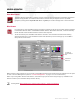
Server Status The Status tab of the Remote window shows, by default, the server’s master output and individual layer streams. Setup The window provides options for how the streams are displayed. Click the view size options and/or use the View drop-down menu to customize. View Size Options Status Tab Display Options Master Output Layer Streams Server status can be setup by dragging components into the status area.
More-detailed layer information can be viewed by dragging a layer icon to the bottom of the status area.
Indicators The Mbox Remote window has several indicators that provide system information. Server Name and IP Server Status Indicator Layer Opacity Playback Position Timecode Server status - The color-coded dot in the Servers column indicates the running status of the server: + Green - Server connection good, Mbox running in Fullscreen mode. + Green/Yellow Flashing - Server connection good, Mbox running in Window mode. + Yellow - Server connection good, Mbox not running.
Flags "Flags" are another type of indicator that may appear to the right of a layer thumbnail during operation. The flags indicate various conditions, some that need to be resolved for proper playback. Hovering the cursor over either of the thumb images for the layer will bring up a tooltip explanation.
CONTENT MANAGEMENT Overview About Mbox Remote Content Management The Mbox Remote Content Management system allows quick and easy management of content between Mbox servers.
in the server list with a letter between a-z and a light colored background. For example, Master of Collection "a." is the icon for the + Member - The Member server acts as the "destination" for Content Management in a Collection; This means that the Member will be synchronized to mirror the state of the Master in the Collection. Members are denoted in the server list with a letter between a-z and a dark colored background. For example, is the icon for a Member on Collection "a.
Managing Content In order to manage content, servers must first be added to Mbox Remote. Refer to "Adding Servers" on page 4 for instructions. Configuring Network Bandwidth There are two properties that control the available network bandwidth which the Content Management system will utilize to transfer content. To configure the bandwidth, open the Mbox Remote Preferences window by clicking the Edit Servers button on the main window or pressing [ ,] on the keyboard.
Configuring Server Master/Member Roles In order to start using Content Management, a Master server must be assigned for a given Collection. By default, all Mbox servers are in the same collection (a). IMPORTANT! The Servers area on the left will always display the list of managed servers. After the Collection has been configured, the Status/Content tabs and file detail/history columns at the right side of the window will reflect the content of whichever server is currently selected.
Selecting Content to Sync In order to synchronize files between Master and Member servers, folders must first be added to the managed folders list. To add a folder to the managed list: Step 1. Select Master server. Step 2. Do one of the following: a. At a content folder row (in the Content Tab), mouse-over the blank Sync column. The sync icon will highlight (and a tooltip will appear in the bottom-left corner of the window). Click on the sync icon to manage this folder. b.
Synchronizing Content After a folder has been added to the managed folders list (see previous page), content can then be synchronized. The window allows for synchronization of a single file, a single folder, or multiple folders. Step 1. To start synchronization from the Master to the Member servers, do one of the following: a. At a folder, click its white Sync icon to synchronize all files in that folder. b.
Note: A file’s new sync status will be reflected in the window approximately 10 seconds after it has been changed. Note: Files with extensions not recognized by Mbox will not be indexed. These will be placed at the bottom of the file list. File(s) not indexed Synchronizing Pixel Map, Alignment Rectangle, and Script Files Pixel mapping files, Alignment Rectangle .plists, and scripts can also be synced between servers using Content Management.
Organizing Content Files Organization of a server's media files is completely under user control using the Mac Finder, rather than a large opaque database. Any changes to name, index number, or file extension can be done using the Mac Finder. As a convenience, folders and files can be quickly viewed in the Finder by selecting the Reveal in Finder option from the pop-up menu. (Note that this only applies to the local machine.
Content Management Archive Each server can be configured to use a specific percentage of the free disk drive space to store archived content files as result of deletions or replacements during synchronization. Archives will be stored in the /Mbox/archive// / where the file name will be a time/date stamped version of the archived file. When the archive runs out of space, the oldest files (by date) are deleted from the archive until there is enough space available.
File Conflicts During synchronization, file conflicts can occur as a result of the following: + Two files in the same folder with the same Index number. + Two folders with the same Index number. Other issues can be caused by: + Folder permissions. + Insufficient disk space.
Monitor and Manage Modes Mbox Remote includes two modes for managing and monitoring the Content Management system. + Manage - allows the Mbox Remote application to perform Content Management actions. + Monitor - allows the Mbox Remote application to monitor Content Management operations. Mbox Remote automatically assumes the Manage role. Typically, no action is required unless the Remote application is run on more than one machine.
SETTING SERVER PREFERENCES Setting Mbox Server Preferences Remotely If you select a server or layer on the Remote main window and then press [ P], the Mbox Server Preferences window will open. This window allows you to remotely set the preferences of the server: Art-Net Universe, Number of Layers, Alignment Rectangles. To edit a setting, click inside the box that surrounds the name of the setting. The preference will become active so that it can be edited.
Step 6. Use Line field to enter a lineweight for the rectangle. (The default lineweight is 1.) Step 7. Use Col (Color) pop-up to specify a color. Step 8. Specify a Screen and Group as required. Step 9. Press "Set" button to apply rectangle settings. If rectangles are not currently being displayed, all rectangles in the selected group will appear briefly to show the location of the new rectangle.
Timecode Window To toggle the Timecode window on and off, press [ T] on the keyboard. + Source - choose the appropriate source for timecode: Generator, Audio In Left, Audio In Right, or MTC (MIDI timecode). + Output - Local (internal routing only), or an active Ethernet port (for sending timecode over the network to Mbox servers). + Auto-Start - enabling this will cause timecode be active as soon as the Remote application launches.
PROJECTION MAPPING Projection Mapping is an advanced Mbox feature. If you are unsure about its operation, contact PRG support for assistance. Overview The Mbox Remote application can used to configure output settings for simple keystone, warp, and multihead output. Beyond those settings, projection surfaces (Topography files) and more complex projection mapping settings can be created, applied, and adjusted for use with Mbox Designer and Mbox Studio only.
Step 3. Press [ P] to open the Mbox Server Preferences window and scroll down to the settings called "Output 1 Identity" and "Output 2 Identity." (You may have to click off then back on the server in the browser window to refresh the Server Preferences window.) Step 4. By default the Output Identity preferences will both be set to a value of "0". Do one of the following: a.
Step 6. Press [ E] to open the Projection Editor window. At the top of the Projection Editor window, you will see the name of the selected server and the two Identity values in parentheses - e.g. "Mbox123 (1,2)". On the left side of the Editor window you will see a column listing the two Output Identities belonging to the selected server. To edit the settings for an output, select the appropriate Identity in this column.
Basic Mode Setup of Output and Keystone/Warp In Basic Mode, the first step to configuring the output is to select the number of outputs that each physical video output on the Mbox server computer is using. Depending on the computer used, each Mbox server can have up to two (2) physical video outputs. Through the use of multi-head adapters, each of these video outputs can be split into up to three (3) outputs. (For this purpose, use a dual/triple head adapter product such as Matrox TripleHead2GO.
Step 4. On the Output Setup tab, you will now see a pop-up labeled "Output 1 of 2" that allows the selection of each multihead output for editing. Below this pop-up is a label stating the actual resolution of this output. In a 2x1 Output setup, this will be ½ of Mbox's FullScreen Mode resolution. Below this you will see two tabs labeled "Texture" and "Keystone/Warp." The Texture tab will be set correctly for you, but may be edited as required to adjust image position and scale.
Other Texture settings are: + Flipped - Reverses the image (left to right) as if seen in a mirror. + Rotation - Sets an arbitrary rotation of the texture around the center of the topo. + Grid Delay - If a value greater than 0 is entered, whenever edits are made to the topo's properties, the topo's mesh will appear for that number of seconds. (This is useful for highlighting the object being edited in order to understand the impact of the edits.
Projection > Output Setup > Keystone/Warp You must create a keystone/warp setup for each output in a multihead setup. To to this, select Create Keystone/Warp from the Options pop-up to enable Keystone or Warp functionality. The interface will default to Keystone mode. Switch to Warp mode by clicking on the relevant radio button at the bottom of the window.
Warp mode is shown as a 3x3 array of rectangles, with all nine of the rectangles having a large, blue point. Warp mode allows you to adjust the four corners by changing the position of the four corner points and to adjust the intermediate curve using the other points. The warp is drawn as a Bezier curve between the corner points, using the intermediate points as the third point on the curve.
Multihead Setup First, connect the multihead adapter to the computer and confirm that the computer sees the adapter and that you are able to output the desired resolution from the desktop. If the desktop can't run at the desired resolution, then Mbox can't either. (Some devices may need additional software to tell the computer what to do or to reprogram the EDID in the device.) Next, determine the resolution that needs to be sent to the multihead adapter.
At this point, the settings can be adjusted to affect the overlap between the two halves, the blend, the aspect ratio, and the orientation. A keystone or warp may be added as described in the previous section (refer to page 31). To reset the settings, you can either press the Configure button again and enter some other multihead and overlap settings, or return to the Options pop-up and select Clear Output Settings.
Advanced Mode (Mbox Designer/Studio Only) Advanced Projection Setup The Advanced Projection mode is enabled by checking the checkbox in the Mbox Remote Preferences window. (Open the Remote Preferences window by clicking the Edit Servers button on the main window or pressing [ ,] on the keyboard.) Projection > Output Setup In Advanced Projection mode, the Output Setup tab is the same except for the addition of a field for entering a model (i.e. object) file for use as the keystone rendering surface.
CAUTION! Models created by external 3D modelling applications may not be appropriate for use as shutters or as keystone rendering surfaces. Great care must be taken in UV mapping such objects when they are created. This functionality is best matched with the simpler Topography (topo) objects created by the Mbox system. If you are using model files on individual playback layers within Mbox as a tool for projection mapping, it is not recommended that you also try to use a keystone model.
Camera Control Descriptions: + Orthogonal checkbox: disables perspective rendering and forces camera position to center. Used for flattening view, affects aspect and texture mapping on 3D objects. + Bearing: camera's horizontal angular offset from the Z axis. + Distance: camera's horizontal distance from the origin. + Eye Position: camera location. - X: camera's distance from the origin along the X axis. - Y: camera's distance from the origin along the Y axis.
The initial step in using topo file is to create the base object. With the Topography > Geometry or Topography > Texture tabs selected, select New Topography… from the Options pop-up. In the window that appears, there are five settings to configure for the new topo file. + Folder.File: 8-bit index number for the topo object file that you are creating. This must be a unique index that does not currently exist.
Topography > Geometry The Geometry tab allows you to define the position, rotation, size, and curvature of the selected topo file. + Origin: anchor point for the topo object's position coordinates. + Position: object's home position in 3D space. + Size: object's size. W refers to width, D refers to depth, T refers to thickness. The different topo objects make different use of the three dimensions depending on their geometry. (Note: the T setting is not used for Meshes and Pixel Rects.
Topography > Texture The Texture tab allows you to define how a texture will be applied to the topo object. Generally topo objects are created for specific texture sizes (movie or still image content). Different-sized content can be applied to topo files, but some amount of scale, aspect, and position adjustment may be required to properly fit such content on a topo file with mismatched texture settings.
Topography > ModelInfo > Controls (Mbox Designer Only) ModelInfo controls can be added to an object to allow additional Art-Net patched into the Mbox server to modify four aspects of the object - position, rotation, texture position, and opacity. Controls should be added with care and may require consultation with a PRG Mbox specialist before use. To add a control, click on the [+] button. To remove the currently selected control, click on the [-] button.
The Control Parameter refers the property of the layer that the control will affect. + Position - position of the object in 3D (X/Y/Z) coordinates + Rotation - rotation of the object in 3D (X/Y/Z) coordinates + Texposition - position of the texture on the object in 2d (X/Y) coordinates + Opacity - transparency of the object Position, Rotation, and Texposition are well suited for unsigned or offset 8, 16, or even 32-bit controls. Opacity is best suited for an unsigned 8-bit control.
ModelInfo In addition to being able to affect the modelinfo properties of Mbox-created topo objects, Remote also allows you to add modelinfo properties to existing object files (obj, svg). This functionality provides the means to set fixed and emissive properties, override UV mapping, add controls, and apply a keystone/warp. ModelInfo > Properties Refer to "Topography > ModelInfo > Properties" on page 40 for information.
svg/svge Mbox can use svg files for projection mapping, but topo files are far more useful and flexible. [Note: to work with the thumbnail generator for Mbox, the svg file extension must be changed to "svge".] axes - Mbox XYZ different to modeling apps' XYZ!! Mbox labels its 3D axes differently that most 3D modeling applications. Mbox uses a front view version of the axes and most modeling applications use a top view version.
PIXEL MAPPING Overview What is Pixel Mapping? Pixel Mapping is a feature that allows mapping of specific functions of sACN, Color Kinetics KiNET, or Art-Netcontrolled fixtures (RGB, Intensity, CMY, etc.) to each of the pixels in Mbox’s composite video image. Pixel mapping data is generated from the onscreen imagery of the server and may be output from one or more Ethernet interfaces of the Mbox computer.
Ethernet Interface Guidelines If you need to use two different ports for Art-Net input and pixel mapping output, you will need to set up the Ethernet ports of your computer properly. + If you are receiving one protocol for control input and output a different protocol for pixel mapping output, you will almost certainly use two separate Ethernet ports, as the different protocols use different subnets.
sACN - sACN is multicast by default in order to reduce bandwidth (though it can be broadcast or unicast). Up to 63,999 universes are available, with each universe having a priority value to allow devices to receive multiple universes of the same number and use the one deemed most important. Guidelines: + Mbox supports a single, global priority setting for all pixel mapping output via sACN. The value can be changed in the Source settings for each pixel mapping configuration.
Compatibility Between Mbox Versions All versions of Mbox software (Designer, Studio, and Mini) use the same configuration files for pixel mapping. While each version has a different maximum number of pixels (none, 6144, and 3072 respectively), there are no other restrictions or differences between the functionality of Mbox software versions. Pixel mapping (.pmap) files created by Mbox 3.9 are not compatible with older versions of Mbox software. However, Mbox 3.9 supports the import of .
Enabling Mbox Pixel Mapping To enable pixel mapping, the Pixel Map Enable checkbox must be checked in the Mbox Setup window. Checking this box enables the processing of pixel mapping patches and the resulting output. When Pixel Mapping is enabled in the Setup window, the Mbox Master Control parameter can be used to enable/ disable overall pixel mapping output, and to enable/disable the pixel mapping mask feature.
Getting Started Pixel Map Tab Pixel maps are created using the controls available in the Mbox Remote Pixel Map tab.
Session Types When working with pixel mapping configuration files, there are three different "session" types: Offline, Live Editing, and Test Only. The session type will be Offline unless either Live Editing or Test Only is chosen from the Pixel Mapping Session menu available by clicking on the gear icon next to the Session Type Indicator. The indicator text will display the current status (Offline, Live Editing, or Test Only), as applicable.
Offline Offline editing allows pixel mapping configuration files to be created and edited without running Mbox software. In this case, a new or existing pixel mapping configuration file (.pmap) can be opened on the computer that is running Mbox Remote. This mode is useful for creating a configuration in advance without the need for an Mbox server (or license). Guidelines: + The .pmap file to be opened can be local or on any network-connected drive.
Live Editing The Live Editing session allows pixel mapping configuration files to be created and edited while the Mbox Remote application is connected to an Mbox server. In this case, changes made to the file have an immediate effect on the output of the Mbox’s pixel mapping engine. This mode is useful so that the configuration can be tested and adjusted without having to go back and forth between offline editing and live playback to view the results.
Step 3. At Begin Session window, click Create New button. Step 4. At Save dialog, enter a file name and choose a location to save. Step 5. Click Save. Step 6. At Begin Session window, click Begin Session. (Once the file is created, the button will no longer be grayed out.
To begin a live editing session and choose a different file: In this step-by-step example, a pixel mapping file different than the one Mbox is currently using has been edited in Offline mode. Changes to the file have not been saved. Step 1. At Servers list, select required server. Step 2. Click gear icon and select Begin Live Editing session for... Step 3. At Begin Session window, save or discard changes to current file by clicking either Discard Changes, Save, or Save As at left side of window.
Step 5. Once selected, the file will be displayed in the window. Click Begin Session to begin live editing. Copy To Mbox If the current pixel mapping configuration file does not reside on the Mbox server when starting a Live Editing session, the file can be copied to the Mbox server using the Begin Session / Currently Editing window. Step 1. At Servers list, select server where file will be copied. Step 2. Click gear icon and select Begin Live Editing session for... Step 3.
Source The "source" is the surface from which pixel data can be sampled to create a pixel map output. In this case, the source is the final, composited rendering surface of the Mbox server. Note that this surface will not be affected by the overall keystone and warp functionality. The size of the source is based on the rendering surface used, which is different depending on the operating mode: + Single Output mode - rendering surface is the one output.
Calculating source dimensions: The default width (W) and height (H) of a new configuration is 1920 x 1080 as shown in the example below: Control Mode Fullscreen Mode Setup Area Mbox Setup Window Width Height The source’s width and height in pixels are equal to the size of the rendering surface based on the output mode used. This is simple to calculate no matter what mode is used. Use the following guidelines: + All measurements are made in screen pixels.
To setup source : Step 1. Be sure Source tab is selected. Step 2. Enter Width and Height in Dimensions fields. Step 3. Enter a priority value for sACN output, if required. Dimensions sACN Priority Value Source Errors / Auto-Detect During a Live Editing session, the Width and Height fields of the Source tab will color the text red if the value does not match the current dimension for Mbox.
Contexts A "context" is a rectangular area taken from the source area and onto which fixtures are placed. Each context can be some or all of the source area, and has its size specified by width and height settings and its position upon the source specified by X and Y offsets from the top-left corner of the source. The context is laid directly over the source image, and is then divided into rectangular subdivisions. The context is subdivided by assigning width and height values for sub-sampling.
Contexts are configured using the Context controls in the lower portion of the Pixel Map tab. 16 9 Context Grid Add Context Button Selected Context Sample Origin X/Y Sample Width & Height Aspect Ratio Lock Ghosting Level Sub-Sample Width & Height Background Image Selector Protocol Selection + Sample X/Y Origin - a pixel location on the source which marks the top-left corner of the context’s rectangular area.
To add contexts: Step 1. Click Context 1 tab. Step 2. Configure options as required. Note: Mbox fields can perform math operations such as add, subtract, multiply, and divide. For example, if you would like to set the Sample Width for a context at half of 1920, enter 1920/2 in the field then press [Enter] on your keyboard. Step 3. To add additional contexts, click [+] button and configure options. (Each context’s configuration is individual to that particular context.
Context Grid Controls Several special tools are available in the Context Grid area: + Zoom slider - adjusts the zoom level of the current view. + Zoom To Context button - zooms to extents of current view. + Zoom To Selection button - zooms and scrolls so that currently selected fixture(s) are visible. + Snap checkbox - snaps fixture placement to the sample rectangles (when checked).
Fixtures Fixtures are controllable devices placed onto the context. The fixtures are created using profiles, which are then used as reference when individual fixtures are patched. (For more detailed information about profiles, refer to "Fixture Profiles" on page 88.) Fixtures can be added and edited using the Fixture tab. Fixture Tab Guidelines: Fixture Information Table (Patch, Layout, Physical) + Fixtures may have one or more pixels.
Protocols Fixtures can output one of the four available protocols: Art-Net, sACN, KiNET DMXout, and KiNET Portout. Guidelines: + Each fixture’s output data may only use one protocol. + Every fixture placed onto the same context will have the same protocol. To place fixtures that output a second protocol, a new context must be created for those fixtures. (The second context may have identical sample and sub-sample properties as another context.
Step 5. Place more fixtures of the same type by continuing to click within Context Grid, switch fixture type by selecting a new type from the pop-up menu, or turn off placement mode by clicking Place New Fixtures button again or pressing [Esc] on the computer keyboard.
Fixtures Out of Bounds It is possible for a fixture to have some or all of its pixels outside the boundaries of its context, or even the entire source. Pixels that are outside the boundary of their context will not output any pixel mapping level data. Pixels can end up outside the context’s boundary: + If the fixture is positioned such that some of its pixels end up outside the boundary. + If the context or source is resized to be smaller after the fixture has been added to the configuration.
For Art-Net and sACN, the universe defaults to 16 when a new configuration is started. These values increment automatically as fixtures are placed. Press the Find Next button to increment the universe and address fields to the next available address based on currently patched fixtures. (Note that you may need to select the appropriate context before pressing the Find Next button.) These values may be manually changed before a fixture is placed so as to assign different values.
Alert Indicator (total alerts) Layout Tab View Fixtures with overlapping pixels Alert Indicator (total alerts) Patch Tab View Fixtures with overlapping addresses MBOX® REMOTE USER MANUAL 69
Re-Addressing Fixtures When fixtures are first placed onto a context, they are automatically given an address as explained in "Addressing Fixtures" on page 67. If the patch needs to change, however, fixtures can be quickly re-addressed using one of three methods: + Patch table. + Re-Address Fixtures window. + Sequential re-addressing feature. Each of these methods is explained below. Patch Table A fixture’s universe and address can be edited directly in the Patch table.
Re-Address Multiple Fixtures Window The Re-Address Multiple Fixtures window can be used to quickly re-address a large group of fixtures. To assign a new starting point using Re-Address Fixtures window: Step 1. At right side of window, select Fixtures tab. Step 2. At Patch tab, select multiple fixtures (using cmd or shift), then double-click any selected line to open ReAddress Multiple Fixtures window. Step 3. At From Address field, enter new starting address.
Re-Sequence Feature The re-sequence feature can be used to re-address fixtures one by one as they are clicked in the Context Grid To re-address using re-sequence feature: Step 1. At right side of window, select Fixtures tab. Step 2. Click (Re)sequence button to enter re-addressing mode. (The button’s text will change from white to green to indicate mode is active.) Step 3. Enter a start Universe and Address in the fields to the right of the button. Step 4.
Copy and Paste Fixtures A convenient way to quickly add fixtures is to use the copy and paste feature. To copy and paste fixtures: Step 1. At Context Grid, select a fixture or fixtures to copy. (Multiple fixtures can be selected by using click and drag to draw a box around their icons.) Step 2. Press [ C] to copy. Selected Fixtures Step 3. Press [ P] to paste. The pasted fixtures will be automatically selected and conflicts will be shown. Original Fixtures Newly Pasted Fixtures Step 4.
Step 5. At Re-Address Fixtures window, enter a free universe and address. Step 6. Click Commit button. (Conflicts in Patch table will now be resolved.
Fixture Editing To select a fixture for editing, deletion, movement, etc., do one of the following: + Click on its icon in the Context Grid. + Click and drag in the Context Grid to draw a box around the fixture. + Click on the fixture’s line in any of the three Fixture tabs in the table (Patch, Layout, and Physical). Select fixture in context Select fixture in table Multiple fixtures can be selected by using click and drag to draw a box around multiple fixtures in the Context Grid.
Editing Fixture Properties Once a fixture has been added to a context, its properties can be edited. Some of the fixture-level properties can be edited directly in the table when the Fixtures tab is selected. These are: + Patch tab: universe/device, address, group + Layout tab: X position, Y position, and rotation. + Physical tab: name Patch Layout Physical Other fixture-level properties can only be edited using the Edit Fixture window.
To use the Edit Fixture window: Step 1. Open Edit Fixture window using one of the following methods: a. Double-click on fixture’s icon in Context Grid. b. Double-click on fixture’s ctx or fixture name field in Fixture table. c. Select multiple fixtures in Fixture table (using cmd or shift), then double-click on one of the fixture’s ctx or fixture name field. Step 2. At Edit Fixture window make changes to properties as required.
Destinations Once fixtures have been placed onto the Context Grid, their data will need to be routed to a destination. This can be done using the Destinations tab. Destinations Tab Selected Protocol Destinations Menu Table Available Protocols There is a separate area of the Destinations tab for each of the protocols. When the Destination tab is selected, the protocol of the current context will be displayed. A different protocol can be viewed by clicking on the name of the protocol.
To enter discrete destinations, double-click in the blank fields below the default destination and enter the universe/ device number and IP Address for the new destination. The IP address is where all data for fixtures using that destination will be sent. Several different values can be entered in this field. There is a dropdown menu to help with this process if you want to pick a particular interface or broadcast IP address.
Destination IP Addressing The configuration of the Ethernet interface on your computer and the destination IP address on the Destinations tab of the fixture table should be coordinated. Destination IP addresses determine both how the outgoing pixel mapping packets are addressed, but also which Ethernet interface on your computer they will be output from. (Refer to "Appendix A. Networking For Mbox" on page 102 for more detailed information.
that will work. Depending on your requirements and other devices on the network, you may require different settings. Refer to "Appendix A. Networking For Mbox" on page 102 for more information on subnet masks. Note: It is possible to receive control data and output pixel mapping data from the same interface on the computer, but this is not recommended except in very simple configurations with only a few universes of data both in and out.
Pixel Map Network Sources and Destinations example diagram: Fixtures Universes 16 - 86 etc... Interface 2 IP Address: 2.0.0.124 Subnet Mask: 255.0.0.0 Interface 1 IP Address: 2.1.0.123 Subnet Mask: 255.255.0.0 Pixel Map Output: Art-Net Universes 16 - 86 Control Input: Art-Net Universes 0 & 1 Mbox Computer IP Address: 2.0.0.1 Subnet Mask: 255.0.0.
Previsualization A previsualized version of the pixel mapping output can be viewed within the Mbox application. The previsualization can be recalled from the computer’s keyboard (using the F5 key) or via external control signal (using DMX values on the Master control channel parameter). There are ten (10) discrete views. The first view is the combined overall previsualization, all contexts overlaid, with the highest numbered context on top. (Note that some contexts may be obscured.
The DMX Ghosting control on each context can be used to adjust the visibility of patched fixtures on the context against the background of the sub-sampling for the context. The control defaults to 25%, at which point the context view will display the pixels of patched fixtures at full brightness and unused areas at a reduced intensity. This enables better visualization of the setup (both context sizing and fixture placement) without needing to connect the actual pixel mapping fixtures.
Background Image A background image can be added to a context in order to better visualize the pixel mapping configuration. The background type can either be a still image or a live stream image. Sample Background Image Selected Context Context Aspect Ratio (Sub-Sample) Background Image Settings Still Image Backgrounds A still image must be in JPEG or a PNG format. A PNG can have an alpha channel (transparency). The image is imported and saved within the pixel map (.
Server Media Content Live Stream Background Ghosting When using a background image, the ghosting level will adjust the brightness of patched fixtures against the background image. The ghosting level may need to be re-adjusted to give the desired level of brightness when using the pixel mapping HUDs in Mbox. To set a background image: Step 1. At context, click on Background Image pop-up menu. Step 2. Select None, Live stream, or Import image from file... Step 3. Configure settings as required.
To delete unused images: If the pixel mapping file contains unused images, these can be deleted to reduce overall file size. Step 1. At context, click on Background Image pop-up menu. Step 2. Select Delete unused images. Any unused images will be deleted from the file.
Fixture Profiles The fixture reference model used with Mbox pixel mapping allows for rapid global changes to all patched fixtures of one type. Mbox provides built-in fixture profiles, as well as the ability to create custom fixture profiles (see below). Custom fixture profiles are saved in the pixel mapping configuration (.pmap) file, while built-in profiles are not saved since they are resident in the application itself.
Profile Level properties: + Profile Name - the profile name used by patched fixtures (for the referencing model). Note that this is not the same as the name of a patched fixture! + Level - overall level mastering. (This value can’t be changed live, only by editing the fixture.) + Mask - property that allows the fixture’s color output to be forced to zero when the correct control values are sent. (This is intended for use with CMY fixtures when HTP merging.
Step 3. Enter necessary values/properties for the pixels in the fixture. (Refer to the explanations and guidelines above.) All active pixels must be of the same type to begin with, but can be changed in a later step (see below). Step 4. Click Generate Array button to create the initial arrangement of pixels. 1 2 3 4 The sequencing pattern in the array is determined by the Pixel Sequencing settings Step 5. Once the initial array has been created, various properties can be changed: a.
Parked Pixels When editing a fixture or a profile, individual pixels included in the fixture can be "parked" at a specific (static) level so as to override the RGB data that would be taken from the source, or to provide output levels for additional channels that might otherwise sit at a level of 0. For example, setting static values for pan and tilt on moving light fixtures. The park values are entered in the Pixels table at the right side of the Edit Fixture Profile window.
The pixel type is chosen in the type pop-up menu: Park Syntax Guidelines: + If multiple values are expressed in one line they must be separated by commas. + Do not use commas in numbers greater than 999 (e.g., use 65535 not 65,535). + RGB = R,G,B color ordering as three 8-bit values (e.g., 127,255,0). This would be the same for CMY, CYM, BGR, etc. The color is always expressed in RGB order, and therefore, Mbox will re-order the values appropriately.
In the fixture editor, if a fixture profile has pixels with parked values the parked values will be displayed on the profile tab - in grey to show they are not editable there. They can also be seen on the overrides tab - where they will be white if not overridden or magenta if overridden. Editing Fixture Profiles Custom fixture profiles can be edited at anytime after they have been created.
Both methods result in the same window opening, allowing the profile to be edited. (If it was created as a copy of a built-in profile, this will be noted in the window title as shown below.) Importing Profiles Fixture profiles can be imported from other Mbox pixel mapping configurations including .pmap files (Mbox v3.9) and .plist files (Mbox v3.8 and earlier). To import profiles: Step 1. At Fixture Profile menu, select Import Profiles... Step 2.
Groups The Groups feature provides an additional input universe for added control of the pixel mapping output. Groups can be used for: + Live-mastering of output levels for some fixtures while not affecting others. + Disabling (zero output) fixtures without affecting others. + Adjusting color balance (subtractive mix) of fixtures without affecting the content or other fixtures. + Replacing the color generated by Mbox with color values supplied by a lighting console without the use of a merge system.
The Intensity Master is inhibitive. The color channels work no matter if the fixture is RGB or CMY, however, the fixture on the lighting console should be patched in RGB order. If the console has an advanced color picker, then this can be used with CMY sliders while still outputting RGB values. The protocol used to control the groups must be the same as the protocol selected for control of Mbox. (As set in the Mbox Setup window.
Testing The Testing feature provides a way to easily locate and test fixtures in order to verify the correct pixel mapping configuration. During testing, selected fixtures can be highlighted statically or flashed between highlight and lowlight states. (This testing functionality mimics highlight/lowlight functionality in lighting consoles.) The Testing feature can be used while Mbox Remote is in a Live Editing session or a Test Only session.
Step 4. At bottom right of window, select Testing tab then click Test button. (The Testing tab text will be displayed in green and the Test button will be dark gray to indicate that the Testing mode is active.) Step 5. Once the Text button is clicked, the selected fixtures will start flashing between the specified highlight and lowlight colors. (The rings around the fixtures represent the actual values sent to the fixtures.) a.
Import/Export Mbox Remote has the ability to import and export pixel mapping fixture data. The Import/Export window is used for this purpose.
Note: The csv import/export tool is intended for the creation of large or complex pixel mapping configurations from automatically generated data. Beyond a certain point it can be quicker to create a script to convert some other data into position and patch information, and save that in a csv format rather than attempting to place and patch the same fixtures individually using Mbox Remote. The import functionality requires that the csv file be formatted properly for handling by Mbox Remote.
Errors will occur if any required formatting is missing. For example, if commas are missing then the entire fixture will be ignored and an error such as the one below will be displayed: + If commas are included, but values are missing, default values will be substituted as follows: - fix_reference - fixture will be ignored (not imported) - fix_univ - univ = 0 - fix_addr - addr = 0 (this is invalid) - fix_xpos - xpos = 0 - fix_ypos - ypos = 0 + Each line must end in a standard line feed/carriage return.
APPENDIX A. NETWORKING FOR MBOX Concepts The majority of communications to and from Mbox use Ethernet protocols. This means Ethernet networks route the data into the Mbox server and from the server to other connected devices. Because all of these protocols need to live in harmony, steps need to be taken to avoid interference between protocols, and to maximize the available network bandwidth/speed.
How the IP Address and Subnet Mask Work Together For a device with the IP address of 192.168.0.123 and a subnet mask of 255.255.0.0, the first two octets of the IP address "192.168" are used to specify the sub-network, and the last two octets "0.123" specify the device's unique identifier within that network.
It is possible for interfaces to send packets to or receive packets sent to a multicast address without joining the corresponding multicast group. But unless the interfaces join the multicast group, switches between the devices may not forward the multicast packets correctly. Most of the time you can use a /8 subnet mask (255.0.0.0) with Mbox.
KiNET KiNET is intended to be unicast only. Therefore all packets are addressed to specific IP addresses. This is efficient, but as with Art-Net unicast, the user must know all of the IP addresses of the connected devices that they want to communicate with. Also, the Mbox computer must still have a port that is on the same subnet as the receiving device.
Notes 106 MBOX ® REMOTE USER MANUAL
Mbox® Remote User Manual Version as of: December 19, 2014 PRG part number: 02.9800.0005.
Production Resource Group, LLC Dallas Office 8617 Ambassador Row, Suite 120 Dallas, Texas 75247 www.prg.