WP & WPS Series Work Positioners Installation, Operation and Service Manual Model Number ___________________ Serial # _________________________ Date placed in service _____________ IMPORTANT: READ CAREFULLY BEFORE INSTALLING OR OPERATING LIFT Part orders are subject to a $50 miminum charge.
This manual was current at the time of printing. To obtain the latest, most updated version, please contact Presto Lifts Customer Service Department or go to our website: www.PrestoLifts.com -- you will find a complete list of current owner’s manuals to print.
CONTENTS Section Page Number SECTION 1: Introduction ................................................................................................. 3 SECTION 2: Safety ........................................................................................................... 3 SECTION 3: Installation ................................................................................................... 3 A. Inspection B. Removing From Pallet SECTION 4: Operation ...........................................
SECTION 1 INTRODUCTION This manual attempts to provide all of the information necessary for the safe and proper installation, operation and maintenance of Presto’s Battery Operated Work Positioner. It is important that all personnel involved with the installation, maintenance or operation of the Work Positioner read this manual. Additional manuals are available at www.prestolifts.com The battery-operated Work Positioner is equipped with a data plate that has a serial number and model identification.
• • • • Check for signs of damage especially to the back cabinet that houses the battery, electrical/hydraulic power pack. Check all connections for tightness. Is there hydraulic fluid visible? Check base frame for dimensions and structural integrity. Inspect for any bent or damaged metal parts. B. REMOVING FROM PALLET: Remove all packaging materials prior to removing the lift from the pallet. Visually inspect the lift as closely as possible.
B. DAILY OPERATIONS MAINTENANCE 1. CHECKS: Battery A. Check for corroded and loose terminals. A white powder substance will be present if there is any existing corrosion. 2. B. Check for loose battery tie-downs. C. Visually inspect for any cracks or damage to the casing. Charger A. Inspect wire connections. 3. B. Check power cord for nicks/damage. C. Check charger for proper mounting. Hydraulic System A. Inspect pump and cylinder for oil leaks. 4. B. Check hydraulic oil level.
B. Clean battery compartment area. C. Check specific gravity -- fully charged battery should read 1265. D. Check fluid level in all cells. Fill with distilled water as necessary to bring fluid to within ¾” of the top. 2. Hydraulic System A. Clean and inspect hydraulic cylinder. 3. B. Lubricate chains with a rust inhibitive chain lubricant. C. Check chain tension. The chains should be tight enough so that they do not come off the chain roller assembly.
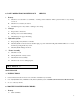
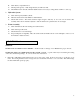
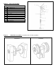
Figure 1: Model WP WP Component Identification Description Item 1 2 3 4 5 6 Cylinder Flow Control Valve Chain Roller Assembly Load Wheel Floor lock Assembly Lead Wheel Figure 2: Model WPS WPS Component Identification Description Item 1 2 3 4 5 6 Figure 3: Cylinder Flow Control Valve Chain Roller Assembly Load Wheel Floor lock Assembly Lead Wheel WP & WPS Rear View Component Identification of Rear View of WP and WPS Item Description 4 5 6 7 8 9 10 11 12 Load Wheel Floor lock Assembly Lead Wheel Sl
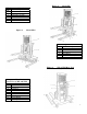
Table 1: Steering Components Item Number 1 2 3 4 5 6 7 8 9 10 10 11 12 13 14 15 16 17 18 18 19 20 20 20 20 Figure 4: Steering Assembly Item and Part Numbers Description and Part Number N0338 - Washer N0817 - Bolt N0250 - Washer, Lock 1004-026 - Bearing 72045-6 - Shaft, Collar 1004-006 - Bearing Holder 1004-010 - Bar, Actuator 1004-043 - Pivot Assembly 1004-025 - Collar With Set Screw 1004-042-01 - Pivot Link (WP) 1004-042-02 - Pivot Link (WPS) 1004-030 - Assembly, Actuator 1004-024-01 - Spring 1004-028
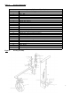
Figure 5: Item 1 2 3 4 5 6 7 8 9 10 11 12 13 Floor Lock Assembly Floor Lock Assembly Detail Description 0574 – Handle, Lock N0180 – Nut, Lock Handle C108 – Spacer N1110 – Bolt, Lock Handle PSL28A – Rings, Retaining PSL28 – Pin PSL25 – Lever, Lock N0180 – Nut, Locking PSL22 – Stud, Adjusting PSL24 – Mount, Rubber PSL26 – Spring, Lock Return PSL21D – Holder, Foot Pad M437 – Pad, Foot Figure 6: Chain Roller Assemblies; Assemblies Only, No Parts Available.
Figure 7: 1000, 1500 & 2700 lb. Cylinder Table 2: Figure 3: Cylinder Parts for 1000 & 3000 Lifts Item Description 1 Cylinder Ram - H108-XXX 2 Inner Cylinder - H106-XXX 3 Outer Cylinder - H101-XXX 4 Bearing Chevron Support - H108A 5 Chevron Set - H109 6 Chevron Spring - H111 7 Ram Guide - H112 8 Washer Ram Guide - H113-2000 9 Nut Ram Guide - H114 10 “O” Ring Cyl.
Figure 9: Work Positioner Back Plate Assembly Work Positioner Back plate Assembly Note Item#1-A & -B include 2 thru 13 11
Item# P/N# Description Qty.
Figure 10: DC Power Wiring Schematic UP/DOWN SWITCH P/N 8256 Figure 11: Old DC Power Pack Figure 12: Old DC Power w/ Remote Control 13
Figure 13: AC Power Wiring Schematic Figure 14: Standard AC Power Pack Figure 15: AC Power w/ Remote Control 14
Figure 16: DC Wiring Schematic w/ Remote Control Figure 17: AC Wiring Schematic w/ Remote Control 15
Table 3: Old Style Replacement Parts* Description Power Pack: A completely assembled DC motor, pump and reservoir with manual control. Call Lee Engineering for part numbers if a Remote Control Power Pack is needed. Power Pack: A completely assembled AC motor, pump and reservoir with Pendant/s. Please specify the voltage and control/s. Pump Body For AC or DC Motor without Remote Control: Includes a B208 Pump Body Gasket. Pump Body For AC or DC Motor with Remote Control: Includes a B208 Pump Body Gasket.
Motor, AC 3/4 HP 115 Volt Motor AC, Power Cord Micro Switch For AC Motor Hand Pendant For AC Power Packs Hand Pendant, Coil Cord For AC Motor Wheel w/ Bearing, 8”x2”, Available Only In Nylon Wheel w/ Bearing, 8”x2”, Available Only In Nylon Wheel w/ Bearing, 3”x3”, Available Only In Nylon Wheel w/ Bearing, 5”, Phenolic Wheel Shaft With Washer Safety Screen, 12” Safety Screen, 24” Safety Screen, 33” Chain Chain Chain Hydraulic Hose, 18” High Pressure Hydraulic Hose, 29” High pressure Hydraulic Hose, 6’ Low Pr
RESTOCKING POLICY Presto Lift, Inc.’s goal is for you to be satisfied with your order. Merchandise may be returned, but returns will be subject to a restocking fee to cover the costs Presto Lift, Inc. incurs which include but are not limited to handling, storage of the units, etc. Presto Lift, Inc. will issue refurbishing costs where end-user wear is apparent. We would prefer to not charge for these costs but find it necessary any apologize for any inconvenience.
RETURN MATERIALS AUTHORIZATION (RMA) PROCEDURES Although Presto Lift, Inc. is not legally obligated to issue a credit for any merchandise, the RETURN MATERIALS AUTHORIZATION (RMA) PROCEDURE is provided as a courtesy to our customers in the event they do not receive what they wanted. If a customer wishes to return a Presto Lift, Inc. product, the first step in the process is to request an RMA number from Presto Lift, Inc.’s Customer Service Department.
Presto Lifts Limited Warranty Policy Presto Lifts warrants all of its products against defects in the welded structural frame and, if applicable, scissor legs from faulty material and workmanship for a period of five (5) years from the date of invoice. A lifetime limited warranty is provided for the Airstroke Actuator in all pneumatic lifts against any defect due to faulty material or workmanship.
21