PC0027 mech 4/12/2000 4:55 PM Page 3 Apollo/Shadowhawk Apollo/Shadowhawk 440S Series User’s Manual u s e r m a n u a l
System Manual
ii Premio System Manual Copyright Premio is a registered trademark of Premio Computer, Inc. All other brands and product names are trademarks or registered trademarks of their respective companies. © 1997 by Premio Computer, Inc. All rights reserved. Printed in Taiwan. Apollo/Shadowhawk, May 2000.
Getting Started iii Contents GETTING STARTED .............................................................. 1 Setting Up ...................................................................................... 2 Switches and Indicators............................................................... 3 UPGRADING .......................................................................... 5 Opening the System Unit ............................................................. 6 Installing an Expansion Card.......
iv Premio System Manual APPENDIX............................................................................ 13 Warranty Policy ...........................................................................13 Service Under Warranty...................................................14 Exclusions from Limited Warranty Programs...................14 FCC Standards ............................................................................15 Important Safety Instructions ..........................................
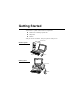
Getting Started Your Premio® system consists of three components: a mid-tower or desktop system unit a keyboard a mouse Add your choice of monitor, and your system is ready to use.
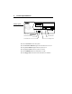
2 Premio System Manual Setting Up To set up your Premio system, simply connect your monitor, the mouse, the keyboard, and any additional components you want to use to the system unit. Follow these easy steps: Power Connector Mouse Connector Keyboard Connector USB Connector Serial-1 Connector Serial-2 Connector Parallel Connector Video Connector Sound Card Connectors 1 Attach your monitor’s video cable to the video connector. 2 Attach the mouse cable to the mouse connector.
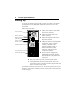
Getting Started 3 Switches and Indicators The system unit’s front panel provides access to the CD-ROM and floppy drives, and to the system’s switches and indicator lights. The illustration below shows a mid-tower system. If you have a desktop system, turn to the illustration on the next page. Mid-tower system The CD-ROM drive reads information on CDs. The floppy drive reads and writes information on diskettes. CD ROM Drive The power switch turns the system on and off.
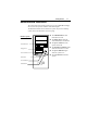
4 Premio System Manual Desktop system Reset Button Hard Drive Indicator Power Indicator Power Switch CD ROM Drive Floppy Drive The reset button restarts the system. The hard drive indicator lights when the hard drive is in use. The power indicator lights when the system is on. The power switch turns the system on and off. The CD-ROM drive reads information on CDs. The floppy drive reads and writes information on diskettes.
Upgrading You can upgrade your Premio system with: Expansion cards More memory An additional hard drive To install an upgrade, you must open the system unit. Before proceeding, read the important cautionary note below. Then follow the steps on the next page. Caution! Static discharge can cause permanent damage to internal electronic components of your computer.
6 Premio System Manual Opening the System Unit Note: Opening the system unit could affect your warranty. Check with the dealer where you purchased your system before opening the system unit. To open the system unit, follow these steps: Mid-tower system 1 Turn off the system and unplug the power cord. 2 Remove the screws securing the side panel (mid-tower) or case (desktop) at the rear of the system unit. Desktop system 3 Slide the side panel or case up and to the rear, and remove it.
Upgrading 7 Installing an Expansion Card To install an expansion card, open the system unit as described on the previous page. Then follow these steps: 1 Remove the screw securing the slot bracket cover for the expansion slot you want to use. Save the screw to secure the expansion card. 2 Insert the expansion card firmly into the slot, making sure it is seated completely. 3 Secure the card with the saved screw.
8 Premio System Manual Installing a Hard Drive To install a hard drive in your system, follow these steps: 1 Disconnect the hard drive cable and power connector. Mid-tower system Desktop system 2 Remove the two screws securing the drive bay. 3 Slide the bay toward the rear of the system unit to remove it. 4 Insert the new drive into an open position in the bay and secure it with four screws. 5 Slide the bay back into the system unit and secure it with two screws. 6 Connect the cables.
Getting Help Troubleshooting Your Premio system is designed to provide years of trouble-free performance. If you have a problem with your system, you may wish to check the information in this section for a quick solution. Monitor Does Not Work If your monitor appears not to be working properly: Check that the monitor’s power cable is securely attached to the monitor and to an outlet that is receiving power.
10 Premio System Manual Keyboard Does Not Work If the NumLock indicator in the upper right corner of the keyboard does not light when the system powers up, or the keyboard does not work: Check that the keyboard cable is securely attached to the system unit’s keyboard connector. If possible, substitute another keyboard that is in good working order. If the substitute works, your keyboard may need replacement.
Getting Help 11 System Unit Problems The fan inside the system unit should make a low, steady sound when operating properly. If the fan is totally silent: Check that the system power cord is securely attached to the back of the system unit and to a power outlet. Verify that the outlet has power. If possible, substitute another power cord that is in good working order. If the substitute works, replace your power cord.
12 Premio System Manual Technical Support You can contact Premio technical support at the following address: Premio Computer, Inc. 918 Radecki Court City of Industry, CA 91748 Telephone: 626.839.3100 Fax: 626.839.3191 Email: support@premiopc.com Web page: http://support.premiopc.com Premio on the Internet Premio maintains a web page on the Internet with the latest information on Premio products, updated drivers, answers to common problems, a troubleshooting guide, and more.
Appendix Warranty Policy Premio Computer, Inc. warrants its line of Premio® computer systems to be free from defects in material and workmanship for a specific warranted period as stated below, from the date of original purchase from Premio Computer, Inc. or a Premio Computer, Inc. authorized reseller. This warranty is contingent upon proper use of the product in question and does not cover products which have been modified or which have been subjected to unusual physical or electrical stress.
14 Premio System Manual Service Under Warranty If this product fails to be in good working order during the warranty period (or specific period of time as noted above), Premio Computer, Inc. will, at its option, repair or replace the product. Repair parts and/or replacement products may be either new or reconditioned at Premio Computer Inc.'s discretion.
Appendix 15 FCC Standards This equipment has been tested and found to comply with the limits for a Class B digital device, pursuant to Part 15 of the FCC Rules. These limits are designed to provide reasonable protection against harmful interference in a residential installation. This equipment generates, uses and can radiate radio frequency energy and, if not installed and used in accordance with the instructions, may cause harmful interference to radio communications.
16 Premio System Manual Important Safety Instructions These instructions are provided by Underwriters Laboratories, Inc. 1. Read all of these instructions and save them for later reference. 2. Follow all warnings and instructions marked on the product. 3. Unplug this product from the wall outlet before cleaning. Do not use liquid or aerosol cleaners. Use a damp cloth for cleaning. 4. Do not use this product near water. 5. Do not place this product on an unstable cart, stand or table.
Appendix 17 that could result in a risk of fire or electric shock. Never spill liquid of any kind on the product. 12. Except as explained elsewhere in this manual, don't attempt to service this product yourself. Opening and removing those covers that are marked “Do Not Remove” may expose you to dangerous voltage points or other risks. Refer all servicing on those compartments to service personnel. 13.
CHAPTER 1 INTRODUCTION Chapter 1 INTRODUCTION The MS-6339 ATX TH1 mainboard is a high-performance computer mainboard based on Intel® 82850 chipset. The MS-6339 is optimized to support the Intel® Pentium® 4 processor for high-end business/personal desktop markets. The Intel® Tehama chipset supports 64B cache line size and a 32bit host addressing, allowing the processor to access the entire 4GB of the chipset’s memory address space.
CHAPTER 1 INTRODUCTION Mainboard Features CPU l Support Intel® Pentium® 4 processor l Supports 1.4GHz or faster Chipset l Intel® Tehama chipset - Up to 2GB maximum memory (RAMBUS).
CHAPTER 1 INTRODUCTION Integrated Super I/O Controller l Winbond W83627HF-AW I/O controller - 1 floppy port supports 2 FDD with 360K, 720K, 1.2M, 1.44M and 2.
CHAPTER 1 INTRODUCTION Mainboard Layout PSFAN SYSFAN Intel 82850 Chipset J5 J8 J9 J10 Bottom: Line-Out Line-In Mic RIMM 4 RIMM 1 Bottom: COM A COM B RIMM 3 Top: LPT RIMM 2 Socket 423 USB Top: Port 2 Bottom: Port 1 Top: Midi/ Game Port ATX Power Supply JWR1 CPUFAN JWR3 Top: mouse Bottom: keyboard J7 FDD AGP Slot IDE2 PCI SLOT 1 IDE1 PCI SLOT 2 BATT + PCI SLOT 3 Intel FW82801BA JUSB1 J15 JBAT1 PCI SLOT 4 JRMS1 J16 JWOL1 JP1 J18 PCI SLOT 5 BIOS CNR JGL1 J17 JGS1 JMDM1
CHAPTER 2 HARDWARE INSTALLATION Chapter 2 HARDWARE INSTALLATION Central Processing Unit: CPU The mainboard operates with Intel® Pentium® 4 processor. The mainboard uses a CPU socket called Socket 423 for easy CPU installation. The CPU should always have a Heat Sink and a cooling fan attached to prevent overheating. • CPU Installation Procedures 1. Pull the lever sideways away from the socket. Then, raise the lever up to a 90-degree angle. Open Lever Sliding Plate 2.
CHAPTER 2 HARDWARE INSTALLATION • CPU Core Speed Derivation Procedure The mainboard CPU Bus Frequency can be set through BIOS setup. If then CPU Clock = 100MHz Core/Bus ratio = 14 CPU core speed = Host Clock x Core/Bus ratio = 1.
CHAPTER 2 HARDWARE INSTALLATION • Fan Power Connectors: CPUFAN/PSFAN/SYSFAN These connectors support system cooling fan with + 12V. It supports three pin head connector. When connecting the wire to the connector, always take note that the red wire is the positive and should be connected to the +12V, the black wire is Ground and should be connected to GND.
CHAPTER 2 HARDWARE INSTALLATION Clear CMOS Jumper: JBAT1 A battery must be used to retain the mainboard configuration in CMOS RAM. Short 1-2 pins of JBAT1 to store the CMOS data. 1 3 JBAT1 1 1 2 2 3 3 Keep Data Note: Clear Data You can clear CMOS by shorting 2-3 pin, while the system is off. Then, return to 1-2 pin position. Avoid clearing the CMOS while the system is on, it will damage the mainboard. Always unplug the power cord from the wall socket.
CHAPTER 2 HARDWARE INSTALLATION Memory Installation • Memory Bank Configuration 2-5 RIMM4(Bank5+ Bank4) RIMM3(Bank4+ Bank5) RIMM2(Bank2+ Bank3) RIMM1(Bank0+ Bank1) The mainboard supports a maximum memory size of 2G. It provides four 168-pin RIMMs sockets. It supports 64 MB to 512 Mbytes RIMM memory module.
CHAPTER 2 HARDWARE INSTALLATION • Memory Installation Procedures A. How to install a RIMM Module 1. The RIMM slot has 2 Notch Keys, so the RIMM memory module can only fit in one direction. 2. Insert the RIMM memory module vertically into theRIMM slot. Then push it in. NOTCH 3. The plastic clip at the side of the RIMM slot will automatically close.
CHAPTER 2 HARDWARE INSTALLATION • Memory Population Rules 1. Support only RIMM. 2. To operate properly, at least two same size168-pin RIMM module must be installed. 3. Support FSB 100MHz: 300/400MHz RIMM 4. Support up to 32 Direct Rambus Device. 5.
CHAPTER 2 HARDWARE INSTALLATION Case Connector: JFP1 The Power Switch, Reset Switch, Power LED, Speaker, HDD LED and Keylock (reserved) are all connected to the JFP1 connector block.
CHAPTER 2 HARDWARE INSTALLATION Power Switch Connect to a 2-pin push button switch. This switch has the same feature with JRMS1. Reset Switch Reset switch is used to reboot the system rather than turning the power ON/ OFF. Avoid rebooting while the HDD LED is lit. You can connect the Reset switch from the system case to this pin. Power LED The Power LED is lit while the system power is on. Connect the Power LED from the system case to this pin.
CHAPTER 2 HARDWARE INSTALLATION Floppy Disk Connector: FDD The mainboard also provides a standard floppy disk connector FDD that supports 360K, 720K, 1.2M, 1.44M and 2.88M floppy disk types. This connector supports the provided floppy drive ribbon cables.
CHAPTER 2 HARDWARE INSTALLATION Hard Disk Connectors: IDE1 & IDE2 The mainboard has a 32-bit Enhanced PCI IDE and Ultra DMA/66 Controller that provides PIO mode 0~4, Bus Master, and Ultra DMA/33/66 function. It has two HDD connectors IDE1 (primary) and IDE2 (secondary). You can connect up to four hard disk drives, CD-ROM, 120MB Floppy (reserved for future BIOS) and other devices to IDE1 and IDE2. These connectors support the provided IDE hard disk cable.
CHAPTER 2 HARDWARE INSTALLATION Power Supply • ATX 20-pin Power Connector: JWR2 ATX 12V Power Connector: JWR1 These connectors support the power button on-board. Using the ATX power supply, functions such as Modem Ring Wake-Up and Soft Power Off are supported by this mainboard. These power connectors support instant power on function which means that system will boot up instantly when the power connector is inserted on the board. Refer to chapter 2-14 for pin definition.
CHAPTER 2 HARDWARE INSTALLATION • ATX 5V/3V Power Connector: JWR3 (optional) This mainboard supports an optional 5V/3V power supply connector. Refer to chapter 2-14 for pin definition.
CHAPTER 2 HARDWARE INSTALLATION PIN DEFINITION TABLE Pin definition for JWR2 PIN 1 2 3 4 5 6 7 8 9 10 20 11 10 1 SIGNAL 3.3V 3.3V GND 5V GND 5V GND PW_OK 5V_SB 12V PIN 11 12 13 14 15 16 17 18 19 20 SIGNAL 3.3V -12V GND PS_ON GND GND GND -5V +5V +5V Pin definition for JWR1 PIN 1 2 3 4 2 1 4 3 SIGNAL GND GND 12V 12V Pin definition for JWR3 1 PIN 1 2 3 SIGNAL GND GND GND PIN 4 5 6 SIGNAL 3.3V 3.
CHAPTER 2 HARDWARE INSTALLATION • Remote Power On/Off Switch: JRMS1 Connect to a 2-pin push button switch. During OFF state, press once and the system turns on. During ON stage, push once and the system goes to sleep mode: pushing it more than 4 seconds will change its status from ON to OFF. If you want to change the setup, you could go to the BIOS Power Management Setup. This is only used for ATX type power supply.
CHAPTER 2 HARDWARE INSTALLATION IrDA Infrared Module Connector: J5 The mainboard provides one infrared (IR) connector for IR modules. This connector is for optional wireless transmitting and receiving infrared module. You must configure the setting through the BIOS setup to use the IR function.
CHAPTER 2 HARDWARE INSTALLATION Serial Port Connectors: COM A and COM B The mainboard provides two 9-pin male DIN connectors for serial port COM A & COM B. These port are 16550A high speed communication port that send/receive 16 bytes FIFOs. You can attach a mouse or a modem cable directly into this connector.
CHAPTER 2 HARDWARE INSTALLATION Parallel Port Connector: LPT1 The mainboard provides a 25 pin female centronic connector for LPT. A parallel port is a standard printer port that also supports Enhanced Parallel Port (EPP) and Extended capabilities Parallel Port (ECP).
CHAPTER 2 HARDWARE INSTALLATION Mouse Connector: JKBMS1 The mainboard provides a standard PS/2® mouse mini DIN connector for attaching a PS/2® mouse. You can plug a PS/2® mouse directly into this connector. The connector location and pin definition are shown below: Pin6 NC Pin5 Mouse Clock Pin3 GND Pin4 VCC Pin1 Mouse DATA Pin2 NC PS/2 Mouse (6-pin Female) Keyboard Connector: JKBMS1 The mainboard provides a standard PS/2® keyboard mini DIN connector for attaching a keyboard.
CHAPTER 2 HARDWARE INSTALLATION Joystick/Midi Connectors You can connect a joystick or game pad to this connector. Joystick/MIDI Audio Port Connectors Line Out is a connector for Speakers or Headphones. Line In is used for external CD player, Tape player, or other audio devices. Mic is a connector for the microphones.
CHAPTER 2 HARDWARE INSTALLATION USB Connectors The mainboard provides a UHCI (Universal Host Controller Interface) Universal Serial Bus root for attaching USB devices like: keyboard, mouse and other USB devices. You can plug the USB device directly to this connector.
CHAPTER 2 HARDWARE INSTALLATION Wake-Up on LAN Connector: JWOL1 The JWOL1 connector is for used with LAN add-on cards that supports Wake Up on LAN function. To use this function, set the “Wake-Up on LAN” to enable at the BIOS Power Management Setup. 1 3 JWOL1 PIN 1 2 3 SIGNAL 5VSB GND MP_WAKEUP Note: LAN wake-up signal is active “high”. Note: To be able to use this function, you need a power supply that provide enough power for this feature.
CHAPTER 2 HARDWARE INSTALLATION Modem Wake Up Connector: JMDM1 The JMDM1 connector is for used with Modem add-on card that supports the Modem Wake Up function. 1 5 JMDM1 PIN 1 2 3 4 5 SIGNAL NC GND MDM_WAKEUP NC 5VSB Note: Modem wake-up signal is active “low”. Note: To be able to use this function, you need a power supply that provide enough power for this feature.
CHAPTER 2 HARDWARE INSTALLATION Power Saving LED Connector: JGL1 JGL1 can be connected with two-color LED. There are two types of LED that you can use: 3-pin LED or 2-pin LED (ACPI request). When the 2-pin LED is connected to JGL1, the light will turn green, when system is On. During sleep mode, the 2-pin LED will change color from Green to Orange. For 3-pin LED, when LED is connected to JGL1, this will light when the system is On and blinks when it is in suspend/sleep mode.
CHAPTER 2 HARDWARE INSTALLATION Power Saving Switch Connector: JGS1 Attach a power saving switch to JGS1. When the switch is pressed, the system immediately goes into suspend mode. Press any key and the system wakes up.
CHAPTER 2 HARDWARE INSTALLATION CD-In Connector: J8 This connector is for CD-ROM audio connector.
CHAPTER 2 HARDWARE INSTALLATION AUX Line In Connector: J9 This connector is used for DVD Add on Card with Line In connector.
CHAPTER 2 HARDWARE INSTALLATION Modem-In: J10 The connector is for Modem with internal voice connector. Mono_Out GND Phone_In J10 Mono_Out is connected to the Modem Speaker Out connector. Phone_In is connected to the Modem Microphone In connector.
CHAPTER 2 HARDWARE INSTALLATION Onboard Audio Codec: JP1 This jumper is used to Enabled/Disabled the onboard Soft audio codec.
CHAPTER 2 HARDWARE INSTALLATION Chassis Intrusion Switch Case: J7 & J15 These connectors are connected to 2-pin connector chassis switch. If the Chassis is open, the switch will be short. The system will record this status. To clear the warning, you must enter the BIOS settting and clear the status.
CHAPTER 2 HARDWARE INSTALLATION Clear BIOS Password: J18 This is used to clear the BIOS password. To clear the password, open pin and restart your computer.
CHAPTER 2 HARDWARE INSTALLATION BIOS Flash Jumper: J17 This jumper is used to lock/unlock BIOS Flash. This jumper should be unlock when flashing/programming the BIOS.
CHAPTER 2 HARDWARE INSTALLATION Case Speaker to Audio Speaker Jumper: J16 This jumper will enable the case speaker/buzzer to be transferred to the Audio speaker.
CHAPTER 2 HARDWARE INSTALLATION USB Front Connector: JUSB1 The mainboard provides a front Universal Serial Bus connector. This is an optional USB connector for Front Panel.
CHAPTER 2 HARDWARE INSTALLATION CNR (Communication Network Riser) The Communication Network Riser specification is an open industrystandard specification that defines a hardware scalable Original Equipment Manufacturer (OEM) mainboard riser board and interface, which supports modem, audio and LAN.
CHAPTER 3 AMI® BIOS USERS GUIDE Chapter 3 AMI® BIOS USER’S GUIDE The system configuration information and chipset register information is stored in the CMOS RAM. This information is retained by a battery when the power is off. Enter the BIOS setup (if needed) to modify this information. The following pages will describe how to enter BIOS setup, and all about options.
CHAPTER 3 AMI® BIOS USERS GUIDE Enter BIOS Setup Enter the AMI® setup Program’s Main Menu as follows: 1. Turn on or reboot the system. The following screen appears with a series of diagnostic check. AMIBIOS (C) 1999 American Megatrends Inc. AGIOMS VXXX XXXXXX Hit if you want to run setup (C) American Megatrends Inc. 61-XXXX-001169-00111111-071592-i82440FX-H 2. When the “Hit ” message appears, press key to enter the BIOS setup screen. 3.
CHAPTER 3 AMI® BIOS USERS GUIDE AMIBIOS HIFLEX SETUP UTILITIES - VERSION 1.30 (C) 1999 American Megatrends, Inc.
CHAPTER 3 AMI® BIOS USERS GUIDE Standard CMOS Setup 1. Press on “Standard CMOS Setup” of the main menu screen . AMIBIOS SETUP - STANDARD CMOS SETUP (C)1999 American Megatrends,Inc.
CHAPTER 3 AMI® BIOS USERS GUIDE BIOS Features Setup 1. Press on “BIOS Features Setup” of the main menu screen. AMIBIOS SETUP - BIOS FEATURES SETUP (C) 1999 American Megatrends, Inc.
CHAPTER 3 AMI® BIOS USERS GUIDE Description of the item on screen follows: Quick Boot Set this option to Enabled to permit AMI® BIOS to boot within 5 seconds. This option replaces the old ABOVE 1 MB Memory Test option. 1st Boot Device/2nd Boot Device/3rd Boot Device This option sets the sequence of boot drives. The settings are: IDE0 The system will boot from the first HDD. IDE1 The system will boot from the Second HDD. IDE2 The system will boot from the Third HDD.
CHAPTER 3 AMI® BIOS USERS GUIDE Floppy Drive Seek When this option is set to Enabled, AMI® BIOS performs a Seek command on floppy drive A: before booting the system. The settings are Enabled and Disabled. The setup and BIOS default settings are Disabled. Password Check This option specifies the type of AMI® BIOS password protection that is implemented. The default settings is Setup. L1 Cache Choosing Write Back allows it to write back the level 1 cache memory.
CHAPTER 3 AMI® BIOS USERS GUIDE Chipset Features Setup 1. Press on “Chipset Features Setup” of the main menu screen. AMIBIOS SETUP - CHIPSET FEATURES SETUP (C) 1999 American Megatrends, Inc. All Rights Reserved CPU Frequency Ratio USB Function USB Keyboard Support Memory Hole Graphics Aperture Size ICH Decode Select CPU Bist Enable ICH Delayed Transaction ICH DCB Enable VGA Frame Buffer USWC PCI Frame Buffer USWC :12.
CHAPTER 3 AMI® BIOS USERS GUIDE Description of the item on screen follows: CPU Frequency Ratio This option enables you to set the CPU ratio. USB Function Set this option to Enabled or Disabled the on-chip USB controller. USB Keyboard Support Select Enabled if your system contains a Universal Serial Bus (USB) controller and you have a USB keyboard. Memory Hole This option allows the end user to specify the location of a memory hole.
CHAPTER 3 AMI® BIOS USERS GUIDE ICH Decode Select This option allows you to select the PCI decode timing of ICH. CPU BIST Enable This option allows you Enable or Disable the CPU Built-In Self Test. ICH Delayed Transaction The chipset has an embedded 32-bit posted write buffer to support delay transactions cycles. Select Enabled to support compliance with PCI specification version 2.1. ICH DCB Enable This option allows you to Enable or Disable the ICH DMA Collection Buffer for LPC I/F.
CHAPTER 3 AMI® BIOS USERS GUIDE Power Management Setup 1. Press on “Power Management Setup” of the main menu screen. AMIBIOS SETUP - POWER MANAGEMENT SETUP (C) 1999 American Megatrends, Inc.
CHAPTER 3 AMI® BIOS USERS GUIDE Description of the item on screen follows: IPCA Function This item allows you to Enabled/Disabled the Advanced Configuration and Power Management (ACPI). The settings are Enabled and Disabled. Sleep State This option allows you to set which Sleep State will be used. S1/POS - Power on Suspend. The S1 sleeping state is a low wake-up latency sleeping state. In this state, no system context is lost (CPU or chipset) and hardware maintains all system context.
CHAPTER 3 AMI® BIOS USERS GUIDE Standby Time Out (Minute) This option specifies the length of a period of system inactivity while in Standby state. When this length of time expires, the computer enters Suspend power state. The settings are Disabled, 1 min, 2 min, 4 min, 8 min, 10 min, 20 min, 30 min, 40 min, 50 min or 60 min.
CHAPTER 3 AMI® BIOS USERS GUIDE Wake Up On Ring/Wake Up On LAN During Disabled, the system will ignore any incoming call from the modem/LAN. During Enabled, the system will boot up if there’s an incoming call from the modem/LAN. Note: If you have change the setting, you must let the system boot up until it goes to the operating system. Then, power off the system. This function will work the next time you power on. Wake Up On PME This option enables the system to comply with PCI specification version 2.
CHAPTER 3 AMI® BIOS USERS GUIDE PNP/PCI Configuration 1. Press on “PNP/PCI Configuration” of the main menu screen. AMIBIOS SETUP - PNP/PCI CONFIGURATION (C) 1999 American Megatrends, Inc.
CHAPTER 3 AMI® BIOS USERS GUIDE Description of the item on screen follows: Clear ESCD During Yes, this will clear ESCD data on every boot. PCI VGA Palette Snoop When this option is set to Enabled, multiple VGA devices operating on different buses can handle data from the CPU on each set of palette registers on every video device. Bit 5 of the command register in the PCI device configuration space is the VGA Palette Snoop bit (0 is disabled).
CHAPTER 3 AMI® BIOS USERS GUIDE IRQ3/IRQ4/IRQ5/RQ7/IRQ9/IRQ10/IRQ11/IRQ14/IRQ15 These options specify the bus that the specified IRQ line is used on. These options allow you to reserve IRQs for legacy ISA adapter cards. These options determine if AMI® BIOS should remove an IRQ from the pool of available IRQs passed to devices that are configurable by the system BIOS. The available IRQ pool is determined by reading the ESCD NVRAM.
CHAPTER 3 AMI® BIOS USERS GUIDE Integrated Peripherals s 1. Press on “Integrated Peripherals” of the main menu screen. AMIBIOS SETUP - INTEGRATED PERIPHERALS (C) 1999 American Megatrends, Inc.
CHAPTER 3 AMI® BIOS USERS GUIDE Description of the item on screen follows: Floppy Controller Set this option to Auto for the BIOS to automatically detect the device Serial Port A/Serial Port B Choose Auto, for the BIOS to automatically detect the device.
CHAPTER 3 AMI® BIOS USERS GUIDE Serial Port B Mode Choosing Normal will set the Serial Port B for normal use, not for IR device. Choosing IrDA or Ask IR will set it for use with IR device using these protocols. IR Duplex Mode Can be set as either Half or Full duplex. IR Pin Select Set this option to IRRX/IRTX when using an internal IR device which is connected to J5 connector. Onboard CIR Port Setting Enabled, the system support consumer IR and your device have to be connected to J5 connector.
CHAPTER 3 AMI® BIOS USERS GUIDE Onboard Parallel Port Choose Auto, the BIOS automatically assigned onboard parallel port to the available parallel port or disabled.
CHAPTER 3 AMI® BIOS USERS GUIDE Port IRQ If the onboard parallel mode is not on auto mode, the user can select the interrupt line for onboard parallel port. We suggest that the user select the interrupt for the onboard parallel port as shown below: Parallel Port IRQ Onboard parallel port set at LPT1(378H) 7 LPT2(278H) 5 LPT3(3BCH) 5 Port DMA Channel This option allows user to choose port DMA channel 1 to 3 for the onboard parallel port on ECP mode.
CHAPTER 3 AMI® BIOS USERS GUIDE Hardware Monitor Setup The Hardware Monitor Setup is used to set the CPU speed and monitor the current CPU Temperature, CPU Fan speed, Chassis Fan Speed, Power fan speed, Vcore, etc. This is only available if there is Hardware Monitor onboard. 1. Press on “Hardware Monitor Setup” of the main menu screen. AMIBIOS SETUP - HARDWARE MONITOR SETUP (C) 1999 American Megatrends, Inc.
CHAPTER 3 AMI® BIOS USERS GUIDE Description of the item on screen follows: Chassis Intrusion Set this option to Enabled, Reset, or Disabled the chassis intrusion detector. During Enabled, any intrusion on the system chassis will be recorded. The next time you turn on the system, it will show a warning message. To be able to clear those warning, choose reset. Afte clearing the message it will go back to Enabled.
CHAPTER 3 AMI® BIOS USERS GUIDE Supervisor/User Password This Main Menu item lets you configure the system so that a password is required each time the system boots or an attempt is made to enter the Setup program. Supervisor Password allows you to change all CMOS settings but the User Password setting doesn’t have this function. The way to set up the passwords for both Supervisor and User are as follow: 1. Choose “Supervisor/User Password” in the Main Menu and press .
CHAPTER 3 AMI® BIOS USERS GUIDE IDE HDD Auto Detection You can use this utility to automatically detect the characteristics of most hard drives. AMIBIOS SETUP - STANDARD CMOS SETUP (C)1999 American Megatrends,Inc.
CHAPTER 4 AWARD® BIOS SETUP Chapter 4 AWARD® BIOS SETUP Award® BIOS ROM has a built-in Setup program that allows users to modify the basic system configuration. This type of information is stored in battery-backed RAM (CMOS RAM), so that it retains the Setup information when the power is turned off.
CHAPTER 4 AWARD® BIOS SETUP Entering Setup Power on the computer and press immediately to allow you to enter Setup. The other way to enter Setup is to power on the computer. When the below message appears briefly at the bottom of the screen during the POST (Power On Self Test), press key or simultaneously press , , and keys.
CHAPTER 4 AWARD® BIOS SETUP The Main Menu Once you enter Award® BIOS CMOS Setup Utility, the Main Menu (Figure 1) will appear on the screen. The Main Menu allows you to select from twelve setup functions and two exit choices. Use arrow keys to select among the items and press to accept or enter the sub-menu.
CHAPTER 4 AWARD® BIOS SETUP Advanced Chipset Features Use this menu to change the values in the chipset registers and optimize your system’s performance. Integrated Peripherals Use this menu to specify your settings for integrated peripherals. Power Management Setup Use this menu to specify your settings for power management. PnP/PCI Configuration This entry appears if your system supports PnP/PCI. PC Health Status This entry shows your PC health status.
CHAPTER 4 AWARD® BIOS SETUP Standard CMOS Setup The items in Standard CMOS Setup Menu are divided into 10 categories. Each category includes no, one or more than one setup items. Use the arrow keys to highlight the item and then use the or keys to select the value you want in each item.
CHAPTER 4 AWARD® BIOS SETUP Date The date format is . Day month date year Day of the week, from Sun to Sat, determined by BIOS. Read-only. The month from Jan. through Dec. The date from 1 to 31 can be keyed by numeric function keys. The year, depends on the year of the BIOS Time The time format is . PrimaryMaster/PrimarySlave SecondaryMaster/Secondary Slave Press PgUp/<+> or PgDn/<-> to select Manual, None, Auto type.
CHAPTER 4 AWARD® BIOS SETUP If the controller of HDD interface is SCSI, the selection shall be “None”. If the controller of HDD interface is CD-ROM, the selection shall be “None”. Access Mode Cylinder Head Precomp Landing Zone Sector The settings are Auto, Normal, Large,LBA.
CHAPTER 4 AWARD® BIOS SETUP Advanced BIOS Features CMOS Setup Utility - Copyright(C) 1984-2000 Award Software Advanced BIOS Features Virus Warning BIOS Flash Write Control CPU L1 & L2 Cache Quick Power On Self Test First Boot Device Second Boot Device Third Boot Device Boot Other Device Swap Floppy Drive Boot Up Floppy Seek Boot Up Numlock Status Gate A20 Option Typematic Rate Setting Typematic Rate (Chars/Sec) Typematic Delay (Msec) Security Option OS Select for DRAM > 64MB HDD S.M.A.R.T.
CHAPTER 4 AWARD® BIOS SETUP BIOS Flash Write Control This option allows you to Enabled or Disabled the BIOS flash write control. CPU L1 & L2 Internal Cache Cache memory is additional memory that is much faster than the conventional DRAM (system memory). When the CPU requests data, the system transfers the requested data from the main DRAM into cache memory, for even faster access by the CPU. Enabled (default) Enable cache Disabled Disable cache Note: The internal cache is built in the processor.
CHAPTER 4 AWARD® BIOS SETUP Boot Up NumLock Status The default value is On. On (default) Keypad is numeric keys. Off Keypad is arrow keys. Gate A20 Option Normal Fast(default) The A20 signal is controlled by keyboard controller or chipset hardware. The A20 signal is controlled by port 92 or chipset specific method. Typematic Rate Setting Key strokes repeat at a rate determined by the keyboard controller. When enabled, the typematic rate and typematic delay can be selected.
CHAPTER 4 AWARD® BIOS SETUP Security Option This category allows you to limit access to the system and Setup, or just to Setup. System The system will not boot and access to Setup will be denied if the correct password is not entered at the prompt. Setup(default) The system will boot, but access to Setup will be denied if the correct password is not entered at the prompt. OS Selection for DRAM > 64MB Allows OS2® to be used with > 64 MB of DRAM. Settings are NonOS/2 (default) and OS2.
CHAPTER 4 AWARD® BIOS SETUP Advanced Chipset Features The Advanced Chipset Features Setup option is used to change the values of the chipset registers. These registers control most of the system options in the computer. Choose the “ADVANCED CHIPSET FEATURES” from the Main Menu and the following screen will appear.
CHAPTER 4 AWARD® BIOS SETUP RDRAM Bus Frequency This will show the RDRAM Bus Frequency during boot-up. The settings are Auto, 400MHz and 300MHz. DRAM Data Integrity Mode This option allows you to select the Parity or ECC (Error-Checking and Correcting), according to the type of installed DRAM. System BIOS Cacheable Selecting Enabled allows caching of the system BIOS ROM at F0000h-FFFFFh, resulting in better system performance.
CHAPTER 4 AWARD® BIOS SETUP AGP Aperture Size (MB) This option determines the effective size of the graphics aperture used in the particular PAC configuration. The AGP aperture is memorymapped, while graphics data structure can reside in a graphics aperture.
CHAPTER 4 AWARD® BIOS SETUP Integrated Peripherals CMOS Setup Utility - Copyright(C) 1984-2000 Award Software Integrated Peripherals OnChip Primary PCI IDE OnChip Secondary PCI IDE IDE Primary Master PIO IDE Primary Slave PIO IDE Secondary Master PIO IDE Secondary Slave PIO IDE Primary Master UDMA IDE Primary Slave UDMA IDE Secondary Master UDMA IDE Secondary Slave UDMA USB Controller USB Keyboard Support Init Display First AC97 Audio AC97 Modem IDE HDD Block Mode Power On Function KB Power On Password KB
CHAPTER 4 AWARD® BIOS SETUP OnChip Primary/Secondary PCI IDE The integrated peripheral controller contains an IDE interface with support for two IDE channels. Select Enabled to activate each channel separately. The settings are: Enabled and Disabled. IDE Primary/Secondary Master/Slave PIO The four IDE PIO (Programmed Input/Output) fields let you set a PIO mode (0-4) for each of the four IDE devices that the onboard IDE interface supports. Modes 0 through 4 provide successively increased performance.
CHAPTER 4 AWARD® BIOS SETUP AC97 Audio This item allows you to decide to Enable/Disable the 850 chipset family to support AC97 Audio. AC97 Modem This item allows you to Enabled or Disabled the AC97 Modem. IDE HDD Block Mode Block mode is also called block transfer, multiple commands, or multiple sector read/write. If your IDE hard drive supports block mode (most new drives do), select Enabled for automatic detection of the optimal number of block read/writes per sector the drive can support.
CHAPTER 4 AWARD® BIOS SETUP UART Mode Select This item allows you to determine which InfraRed(IR) function of the onboard I/O chip, this functions uses. RxD, TxD Active This item allows you to determine the active of RxD, TxD. The settings are “Hi,Hi”, “Lo,Lo”, “Lo,Hi” and “Hi,Lo”. IR Transmission Delay This item allows you to Enabled/Disabled the IR transmission delay. The settings are Enabled or Disabled. UR2 Duplex Mode This item allows you to select the IR half.full duplex function.
CHAPTER 4 AWARD® BIOS SETUP Onboard Parallel Mode To operate the onboard parallel port as Standard Parallel Port only, choose “SPP.” To operate the onboard parallel port in the EPP modes simultaneously, choose “EPP.” By choosing “ECP”, the onboard parallel port will operate in ECP mode only. Choosing “ECP + EPP” will allow the onboard parallel port to support both the ECP and EPP modes simultaneously. The ECP mode has to use the DMA channel, so choose the onboard parallel port with the ECP feature.
CHAPTER 4 AWARD® BIOS SETUP Power Management Setup The Power Management Setup allows you to configure you system to most effectively save energy while operating in a manner consistent with your own style of computer use.
CHAPTER 4 AWARD® BIOS SETUP ACPI Suspend Type This item will set which ACPI suspend type will be used. S1 (POS) The S1 sleeping state is low wake-up latency sleeping state. In this state, no system context is lost (CPU or chipset) and hardware maintains all system context. S3 (STR) The S3 state is a low wake-up latency sleeping state where all system context is lost except system memory. CPU, cache, and chipset context are lost in this state.
CHAPTER 4 AWARD® BIOS SETUP Video Off In Suspend This determines the manner in which the monitor is blanked. The settings are Yes and No. Suspend Type Select the Suspend Type. The settings are: PWRON Suspend, Stop Grant. Modem Use IRQ This determines the IRQ in which the MODEM can use. The settings are 3, 4, 5, 7, 9, 10, 11and NA. Suspend Mode When enabled and after the set time of system inactivity, all devices except the CPU will be shut off.
CHAPTER 4 AWARD® BIOS SETUP Power On by Ring During Disabled, the system will ignore any incoming call from the modem. During Enabled, the system will boot up if there’s an incoming call from the modem. Wake-Up on LAN To use this function, you need a LAN add-on card which support power on functions. It should also support the wake-up on LAN jumper (JWOL1). Enabled Wake up on LAN supported. Disabled Wake up on LAN not supported. CPU Thermal-Throttling Select the CPU THRM-Throttling rate.
CHAPTER 4 AWARD® BIOS SETUP Reload Global Timer Events Reload Global Timer events are I/O events whose occurrence can prevent the system from entering a power saving mode or can awaken the system from such a mode. In effect, the system remains alert for anything which occurs to a device which is configured as Enabled , even when the system is in a power down mode.
CHAPTER 4 AWARD® BIOS SETUP PnP/PCI Configuration Setup This section describes configuring the PCI bus system. PCI, or Personal Computer Interconnect, is a system which allows I/O devices to operate at speeds nearing the speed the CPU itself uses when communicating with its own special components. This section covers some very technical items and it is strongly recommended that only experienced users should make any changes to the default settings.
CHAPTER 4 AWARD® BIOS SETUP Reset Configuration Data Normally, you leave this field to Disabled. Select Enabled to reset Extended System Configuration Data (ESCD) when you exit Setup if you have installed a new add-on and the system reconfiguration has caused such a serious conflict that the operating system can not boot. The settings are Enabled and Disabled .
CHAPTER 4 AWARD® BIOS SETUP PC Health Status This section shows the Status of your CPU, Fan, Warning for overall system status. CMOS Setup Utility - Copyright(C) 1984-2000 Award Software PC Health Status Chassis Intrusion Detect CPU Warning Temperature Current System Temp Current CPU Temperature Current CPU FAN Current SYS Fan Current PWR Fan Vcore +1.88V Vio +5V +12V -12V -5V VBAT(V) 5VSB(V) Shutdown Temperature Disabled Disabled 39 0C/1020 F 66 0C/1500 F 5532RPM 0RPM 0RPM 1.65V 1.88V 3.24V 4.89V 11.
CHAPTER 4 AWARD® BIOS SETUP CPU Warning Temperature Select the combination of lower and upper limits for the CPU temperature. If the CPU temperature extends beyond either limit, any warning mechanism programmed into your system will be activated. Current System Temp/Current CPU Temperature/Current CPU Fan (optional)/SYS Fan (optional)/PWR Fan/Vcore/ +1.88V/Vio/+5V/+12V/-12V/-5V/VBAT(V)/5VSB(V) This will show the CPU/FAN/System voltage chart and FAN Speed.
CHAPTER 4 AWARD® BIOS SETUP Frequency/Voltage Control This section is for setting CPU Frequency/Voltage Control. CMOS Setup Utility - Copyright(C) 1984-2000 Award Software Frequency/Voltage Control CPU Clock Ratio x8 Item Help Menu Level > ↑ ↓ → ← Move Enter:Select +/-/PU/PD:Value F10:Save ESC:Exit F1:General Help F5:Previous Values F6:Fail-safe defaults F7:Optimized Defaults CPU Clock Ratio The CPU Clock Ratio provides flexibility for overclockers from x8 to x 23.
CHAPTER 4 AWARD® BIOS SETUP Load Fail-Safe/Optimized Defaults Load Fail-Safe Defaults When you press on this item, you get a confirmation dialog box with a message similar to: Load Fail-Safe Defaults (Y/N) ? N Pressing ‘Y’ loads the BIOS default values for the most stable, minimalperformance system operations.
CHAPTER 4 AWARD® BIOS SETUP Set Supervisor/User Password You can set either supervisor or user password, or both of them. The differences are: Supervisor password: Can enter and change the options of the setup menus. User password: Can only enter but do not have the right to change the options of the setup menus. When you select this function, the following message will appear at the center of the screen to assist you in creating a password.
CHAPTER 4 AWARD® BIOS SETUP Additionally, when a password is enabled, you can also require the BIOS to request a password every time your system is rebooted. This would prevent unauthorized use of your computer. You determine when the password is required within the BIOS Features Setup Menu and its Security option. If the Security option is set to “System”, the password will be required both at boot and at entry to Setup. If set to “Setup”, prompting only occurs when trying to enter Setup.
CHAPTER 5 AUDIO DRIVER Chapter 5 CREATIVE AUDIO DRIVER (OPTIONAL) Creative CT5880 The Creative® CT5880 digital controller provides the next generation of audio performance to the PC market. Features l l l l SoundScape WaveTable Synthesizer. Full DOS Game Compatibility. PCI Bus Master for fast DMA. Fully Compliant with PC97 Power Management Specification. System Requirements This section describes system requirements for the Audio Driver installation and Usage.
CHAPTER 5 AUDIO DRIVER Audio Driver Setup Insert the CD-title into your CD-ROM drive. This CD will auto-run. This will display installation for Microsoft Direct X 7.0a, Creative PCI 128 Sound Driver and Intel Inf Update. Please make sure that you have finished the installation for Intel Inf Update before proceeding to install the Audio Driver. To install the audio driver, click on the button for automatic installation.
CHAPTER 5 AUDIO DRIVER Windows® NT 4.0 Audio Driver Installation Procedure: Step 1: Insert the provided CD_ROM disk into the CD-ROM drive. Step 2: Look for the CD_ROM drive, double click on the CD_ROM icon. This will show the setup screen. Step 3: Click on “Creative PCI 128 Sound Driver” icon. Step 4: This will copy the audio drivers into the hard drive. Step 5: A message will appear stating you must restart the Windows® NT 4.0 system, select yes to restart.